Lexus ES: Inspection
INSPECTION
PROCEDURE
1. INSPECT WINDSHIELD WIPER SWITCH ASSEMBLY (w/ Auto Wiper System)
(a) Measure the resistance according to the value(s) in the table below.
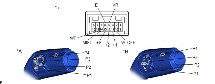
| *A | for Type A | *B | for Type B |
| *a | Component without harness connected (Windshield Wiper Switch Assembly) | - | - |
HINT:
If the result is not as specified, replace the windshield wiper switch assembly.
Standard Resistance:
Front Wiper Switch| Tester Connection | Switch Condition | Specified Condition |
|---|---|---|
| 14 (MIST) - 5 (E) | MIST | Below 1 Ω |
| 10 (W_OFF) - 5 (E) | OFF | |
| 13 (+S) - 5 (E) | AUTO | |
| 11 (+1) - 5 (E) | LO | |
| 12 (+2) - 5 (E) | HI |
| Tester Connection | Switch Condition | Specified Condition |
|---|---|---|
| 15 (WF) - 5 (E) | ON | Below 1 Ω |
| OFF | 10 kΩ or higher |
| Tester Connection | Switch Condition | Specified Condition |
|---|---|---|
| 4 (VR) - 5 (E) | P1 | 1102 to 1218 Ω |
| P2 | 570 to 630 Ω | |
| P3 | 256.5 to 283.5 Ω | |
| P4 | Below 1 Ω |
2. INSPECT WINDSHIELD WIPER SWITCH ASSEMBLY (w/o Auto Wiper System)
(a) Measure the resistance according to the value(s) in the table below.
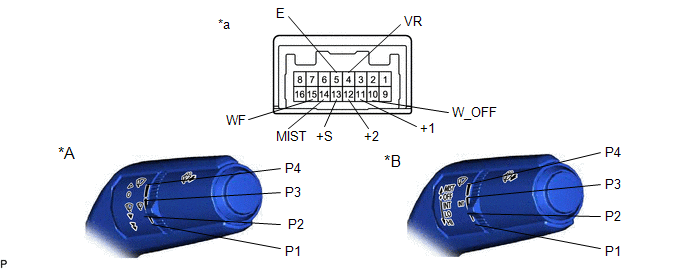
| *A | for Type A | *B | for Type B |
| *a | Component without harness connected (Windshield Wiper Switch Assembly) | - | - |
Standard Resistance:
Front Wiper Switch| Tester Connection | Condition | Specified Condition |
|---|---|---|
| 14 (MIST) - 5 (E) | MIST position | Below 1 Ω |
| Except MIST position | 10 kΩ or higher | |
| 10 (W_OFF) - 5 (E) | OFF position | Below 1 Ω |
| Except OFF position | 10 kΩ or higher | |
| 13 (+S) - 5 (E) | INT position | Below 1 Ω |
| Except INT position | 10 kΩ or higher | |
| 11 (+1) - 5 (E) | LO position | Below 1 Ω |
| Except LO position | 10 kΩ or higher | |
| 12 (+2) - 5 (E) | HI position | Below 1 Ω |
| Except HI position | 10 kΩ or higher |
| Tester Connection | Condition | Specified Condition |
|---|---|---|
| 15 (WF) - 5 (E) | ON position | Below 1 Ω |
| OFF position | 10 kΩ or higher |
| Tester Connection | Condition | Specified Condition |
|---|---|---|
| 4 (VR) - 5 (E) | P1 position | 1102 Ω to 1218 Ω |
| P2 position | 570 Ω to 630 Ω | |
| P3 position | 256.5 Ω to 283.5 Ω | |
| P4 position | Below 1 Ω |
HINT:
If the result is not as specified, replace the windshield wiper switch assembly.
READ NEXT:
 Installation
INSTALLATION PROCEDURE 1. INSTALL WINDSHIELD WIPER SWITCH ASSEMBLY (a) Engage the claw to install the windshield wiper switch assembly as shown in the illustration. Install in this Direction
Vehicle Interior
h1 {color:red;} h2 {color:blue;} h3 {color:green;}
SEE MORE:
System Diagram
SYSTEM DIAGRAM HINT: Each tire pressure warning valve and transmitter sends its transmitter ID, temperature and tire pressure information to the tire pressure warning ECU and receiver. Transmitting ECU (Transmitter) Receiving ECU Signal Communication Method Combination Meter Assembly
Installation
INSTALLATION PROCEDURE 1. INSTALL LUGGAGE COMPARTMENT DOOR WEATHERSTRIP (a) Make sure to remove any non-drying sealant from the installation surfaces on the vehicle body. NOTICE: If there is any non-drying sealant remaining on the vehicle body, the luggage compartment door weatherstrip may not be
