Lexus ES: Inspection
INSPECTION
PROCEDURE
1. INSPECT SOLENOID (SL) VALVE
| (a) Measure the resistance according to the value(s) in the table below. Standard Resistance:
If the result is not as specified, replace the solenoid (SL) valve. |
|
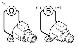
(b) Connect a positive (+) lead from the battery to the terminal of the solenoid (SL) valve connector and a negative (-) lead to the solenoid (SL) valve body, and check that the solenoid (SL) valve moves and makes an operating sound.
NOTICE:
When using battery voltage during the inspection, do not bring the positive (+) and negative (-) tester probes too close to each other as a short circuit may occur.
OK:
The solenoid (SL) valve moves and makes an operating sound.
If the result is not as specified, replace the solenoid (SL) valve.
2. INSPECT SOLENOID (SLT) VALVE
| (a) Measure the resistance according to the value(s) in the table below. Standard Resistance:
If the result is not as specified, replace the solenoid (SLT) valve. |
|
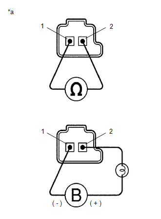
(b) Connect a positive (+) lead from the battery with a 21 W bulb to terminal 2 and a negative (-) lead to terminal 1 of the solenoid (SLT) valve connector, and check that the solenoid (SLT) valve moves and makes an operating sound.
NOTICE:
When using battery voltage during the inspection, do not bring the positive (+) and negative (-) tester probes too close to each other as a short circuit may occur.
OK:
The solenoid (SLT) valve moves and makes an operating sound.
If the result is not as specified, replace the solenoid (SLT) valve.
3. INSPECT SOLENOID (SLU) VALVE
HINT:
Refer to Inspect Solenoid (SLT) Valve.
4. INSPECT SOLENOID (SL1) VALVE
HINT:
Refer to Inspect Solenoid (SLT) Valve.
5. INSPECT SOLENOID (SL2) VALVE
HINT:
Refer to Inspect Solenoid (SLT) Valve.
6. INSPECT SOLENOID (SL3) VALVE
HINT:
Refer to Inspect Solenoid (SLT) Valve.
7. INSPECT SOLENOID (SL4) VALVE
HINT:
Refer to Inspect Solenoid (SLT) Valve.
8. INSPECT SOLENOID (SL5) VALVE
HINT:
Refer to Inspect Solenoid (SLT) Valve.
9. INSPECT SOLENOID (SL6) VALVE
HINT:
Refer to Inspect Solenoid (SLT) Valve.
READ NEXT:
 Installation
INSTALLATION PROCEDURE 1. INSTALL TRANSMISSION VALVE BODY ASSEMBLY (a) Coat 2 new transaxle case gaskets with Toyota Genuine ATF WS and install them to the automatic transaxle case sub-assembly. (b) C
Reassembly
REASSEMBLY PROCEDURE 1. INSTALL SOLENOID (SL) VALVE (a) Coat the solenoid (SL) valve with Toyota Genuine ATF WS. (b) Install the solenoid (SL) valve to the transmission valve body assem
Removal
REMOVAL CAUTION / NOTICE / HINT The necessary procedures (adjustment, calibration, initialization or registration) that must be performed after parts are removed and installed, or replaced during tran
SEE MORE:
Precaution
PRECAUTION PRECAUTION FOR DISCONNECTING CABLE FROM NEGATIVE BATTERY TERMINAL NOTICE:
After the engine switch is turned off, the radio receiver assembly records various types of memory and settings. As a result, after turning the engine switch off, make sure to wait at least 60 seconds before disc
System Description
SYSTEM DESCRIPTION PANORAMIC MOON ROOF SYSTEM DESCRIPTION (a) The panoramic moon roof system controls the sliding roof operation using the sliding roof ECU (sliding roof drive gear assembly) and roof sunshade ECU (sliding roof drive gear assembly). Operating the panoramic moon roof switch (map light
