Lexus ES: Removal
REMOVAL
CAUTION / NOTICE / HINT
The necessary procedures (adjustment, calibration, initialization or registration) that must be performed after parts are removed and installed, or replaced during back window glass sub-assembly removal/installation are shown below.
Necessary Procedure After Parts Removed/Installed/Replaced (for HV Model)| Replaced Part or Performed Procedure | Necessary Procedure | Effect/Inoperative Function when Necessary Procedure not Performed | Link |
|---|---|---|---|
|
*: When performing learning using the Techstream.
Click here | |||
| Disconnect cable from negative (-) auxiliary battery terminal | Perform steering sensor zero point calibration | Lane Control System (for HV Model) | |
| Pre-collision System (for HV Model) | |||
| Parking Support Brake System (for HV Model)* | |||
| Lighting System (for HV Model) | |||
| Memorize steering angle neutral point | Parking Assist Monitor System (for HV Model) | | |
| Panoramic View Monitor System (for HV Model) | | ||
| Initialize power trunk lid system | Power Trunk Lid System (for HV Model) | | |
CAUTION:
Some of these service operations affect the SRS airbag system. Read the precautionary notices concerning the SRS airbag system before servicing.
.png)
Click here .gif)
NOTICE:
- After the power switch is turned off, the radio receiver assembly records various types of memory and settings. As a result, after turning the power switch off, make sure to wait at least 85 seconds before disconnecting the cable from the negative (-) auxiliary battery terminal. (for Audio and Visual System)
- After the power switch is turned off, the radio receiver assembly records various types of memory and settings. As a result, after turning the power switch off, make sure to wait at least 85 seconds before disconnecting the cable from the negative (-) auxiliary battery terminal. (for Navigation System)
| Replaced Part or Performed Procedure | Necessary Procedure | Effect/Inoperative Function when Necessary Procedure not Performed | Link |
|---|---|---|---|
|
*: When performing learning using the Techstream.
Click here | |||
| Disconnect cable from negative (-) battery terminal | Perform steering sensor zero point calibration | Lane Control System (for Gasoline Model) | |
| Pre-collision System (for Gasoline Model) | |||
| Parking Support Brake System (for Gasoline Model)* | |||
| Lighting System (for Gasoline Model) | |||
| Memorize steering angle neutral point | Parking Assist Monitor System (for Gasoline Model) | | |
| Panoramic View Monitor System (for Gasoline Model) | | ||
| Initialize power trunk lid system | Power Trunk Lid System (for Gasoline Model) | | |
CAUTION:
Some of these service operations affect the SRS airbag system. Read the precautionary notices concerning the SRS airbag system before servicing.
Click here
NOTICE:
- After the engine switch is turned off, the radio receiver assembly records various types of memory and settings. As a result, after turning the engine switch off, make sure to wait at least 85 seconds before disconnecting the cable from the negative (-) battery terminal. (for Audio and Visual System)
- After the engine switch is turned off, the radio receiver assembly records various types of memory and settings. As a result, after turning the engine switch off, make sure to wait at least 85 seconds before disconnecting the cable from the negative (-) battery terminal. (for Navigation System)
PROCEDURE
1. REMOVE ROOF HEADLINING ASSEMBLY
Click here
2. DISCONNECT REAR SEAT OUTER BELT ASSEMBLY LH
Click here
3. DISCONNECT REAR SEAT OUTER BELT ASSEMBLY RH
HINT:
Use the same procedure as for the LH side.
4. REMOVE CENTER STOP LIGHT SET
Click here
5. REMOVE REAR SEAT SHOULDER BELT COVER
Click here
6. REMOVE PACKAGE TRAY TRIM PANEL ASSEMBLY (w/o Rear Sunshade)
Click here
7. REMOVE PACKAGE TRAY TRIM PANEL ASSEMBLY (w/ Rear Sunshade)
Click here
8. REMOVE NO. 2 PACKAGE TRAY TRIM PANEL ASSEMBLY (w/ Rear Sunshade)
Click here
9. REMOVE BACK WINDOW GLASS SUB-ASSEMBLY
(a) Disconnect each connector.
(b) Apply protective tape to the area around the installation position of the back window glass sub-assembly on the vehicle body to prevent it from being scratched.
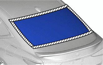
.png) | Protective Tape |
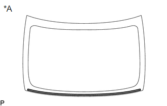
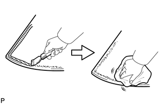
| (c) Using a knife, cut off the back window outside moulding as shown in the illustration. |
|
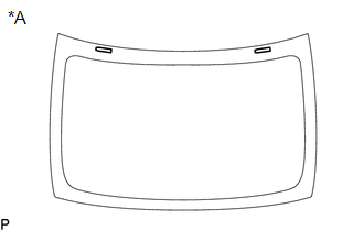
| (d) Place matchmarks on the back window glass sub-assembly and vehicle body at the locations indicated in the illustration. HINT: Matchmarks are not necessary if the back window glass sub-assembly is not going to be reused. |
|
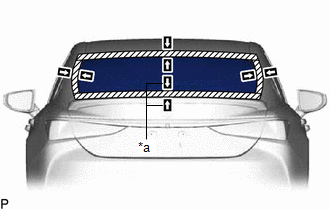
| (e) Pass a piano wire between the vehicle body and back window glass sub-assembly from the interior. |
|
(f) Tie both wire ends to wooden blocks or similar objects that can serve as handles.
(g) Cut off the adhesive by pulling the piano wire around the back window glass sub-assembly.
NOTICE:
- When separating the back window glass sub-assembly, be careful not to damage the paint or interior and exterior ornaments.
- When cutting off the adhesive, take care not to damage the connectors on the back window glass sub-assembly.
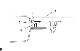
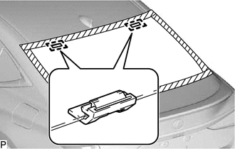
(h) Disengage the back window glass stoppers.
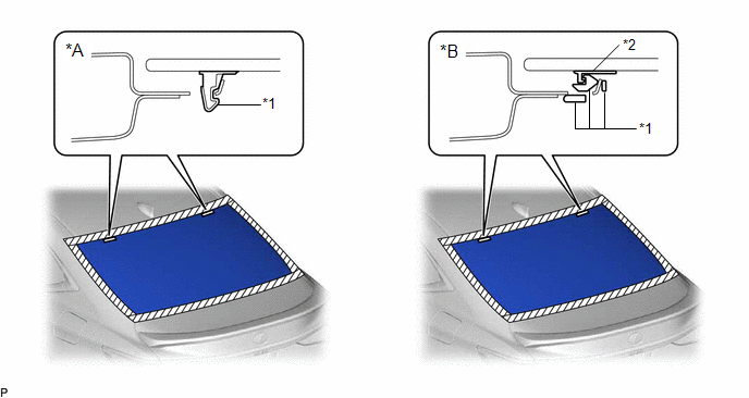
| *A | for 1-piece Type | *B | for 2-piece Type |
| *1 | No. 1 Back Window Glass Stopper | *2 | No. 2 Back Window Glass Stopper |
NOTICE:
- The No. 1 back window glass stoppers and No. 2 back window glass stoppers are installed to the back window glass sub-assembly as shown in the illustration. Be careful not to damage the back window glass sub-assembly when cutting the adhesive.
- To prevent the back window glass sub-assembly from falling when performing this operation, be sure to hold the back window glass sub-assembly using suction cups.
HINT:
Depending on the vehicle, either 1-piece type or 2-piece type stoppers may be present.
(i) Using suction cups, remove the back window glass sub-assembly.
NOTICE:
- Be careful not to drop the back window glass sub-assembly.
- Leave as much adhesive on the vehicle body as possible when removing the back window glass sub-assembly.
10. REMOVE BACK WINDOW GLASS ADHESIVE DAM
(a) When reusing the back window glass:
| (1) Using a scraper, remove the back window glass adhesive dam. NOTICE:
|
|
11. REMOVE NO. 1 BACK WINDOW GLASS STOPPER (for 1-piece Type)
(a) When reusing the back window glass:
| (1) Using a scraper, remove the 2 No. 1 back window glass stoppers. NOTICE:
|
|
12. REMOVE NO. 2 BACK WINDOW GLASS STOPPER (for 2-piece Type)
(a) When reusing the back window glass:
| (1) Using a scraper, remove the 2 No. 2 back window glass stoppers. NOTICE:
|
|

13. REMOVE NO. 1 BACK WINDOW GLASS STOPPER (for 2-piece Type)
| (a) Remove the 2 No. 1 back window glass stoppers. NOTICE: Be sure to replace the No. 1 back window glass stoppers with new ones. |
|
14. CLEAN BACK WINDOW GLASS
(a) When reusing the back window glass:
| (1) Using a scraper, remove any remaining adhesive dam and adhesive residue from the back window glass. NOTICE: Be careful not to damage the back window glass. |
|
(2) Clean the outer circumference of the back window glass with a non-residue solvent.
NOTICE:
- Do not touch the back window glass surface after cleaning it.
- Even if using a new back window glass, clean it with a non-residue solvent.
15. CLEAN VEHICLE BODY
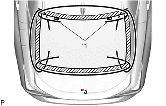
(a) Clean and shape the contact surface of the vehicle body.
(1) Using a knife, cut away excess adhesive on the contact surface of the vehicle body as shown in the illustration.
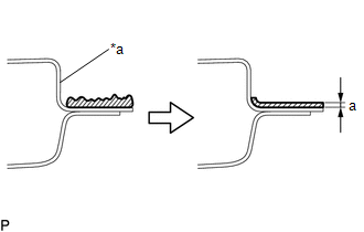
| *a | Vehicle Body |
| | Adhesive |
Standard Dimension:
| Area | Dimension |
|---|---|
| a | 1.0 mm (0.0394 in.) or more |
NOTICE:
Be careful not to damage the vehicle body.
HINT:
Leave approximately 1.0 mm (0.0394 in.) of adhesive on the vehicle body.
(2) Clean the contact surface of the vehicle body with a piece of cloth saturated with non-residue solvent.
HINT:
Even if all of the adhesive has been removed, clean the vehicle body.
READ NEXT:
 Installation
INSTALLATION PROCEDURE 1. INSTALL NO. 1 BACK WINDOW GLASS STOPPER (for 2-piece Type) (a) Install 2 new No. 1 back window glass stoppers to the vehicle body as shown in the illustration. HINT: Only
Front Passenger Side Power Window Switch
ComponentsCOMPONENTS ILLUSTRATION *1 POWER WINDOW REGULATOR SWITCH ASSEMBLY *2 POWER WINDOW REGULATOR SWITCH ASSEMBLY WITH FRONT DOOR UPPER ARMREST BASE PANEL RemovalREMOVAL PROCEDURE 1
SEE MORE:
Cleaning the hybrid battery (traction
battery) air intake vent and
filter
To prevent the fuel economy from
being affected, visually inspect the
hybrid battery (traction battery) air
intake vent periodically for dust and
clogs. If it is dusty or clogged or if
"Maintenance Required for Traction
Battery Cooling Parts See
Owner's Manual" is displayed on
the multi-info
Power Trunk Lid does not Operate Using Outside Switch
DESCRIPTION The door control switch signal is sent to the luggage closer motor assembly. If the power trunk lid does not operate using the door control switch, a door control switch circuit malfunction is a possible cause. WIRING DIAGRAM CAUTION / NOTICE / HINT NOTICE: If the luggage closer motor a
