Lexus ES: Installation
INSTALLATION
PROCEDURE
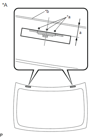
1. INSTALL NO. 1 BACK WINDOW GLASS STOPPER (for 2-piece Type)
| (a) Install 2 new No. 1 back window glass stoppers to the vehicle body as shown in the illustration. HINT: Only 2-piece type back window glass stoppers are provided as supply parts. Use 2-piece type stoppers as replacements even if 1-piece type stoppers were originally installed. |
|
.png)
2. INSTALL NO. 2 BACK WINDOW GLASS STOPPER (for 2-piece Type)
(a) Using a brush or sponge, coat the installation area of 2 new No. 2 back window glass stoppers with glass primer.
NOTICE:
- Do not apply too much glass primer.
- Allow the glass primer to dry for 3 minutes or more.
- Throw away any leftover glass primer.
HINT:
If an area other than specified is coated by accident, wipe off the glass primer with a clean piece of cloth before it dries.
| (b) Install 2 new No. 2 back window glass stoppers to the back window glass as shown in the illustration. Standard Dimension:
HINT: Only 2-piece type back window glass stoppers are provided as supply parts. Use 2-piece type stoppers as replacements even if 1-piece type stoppers were originally installed. |
|
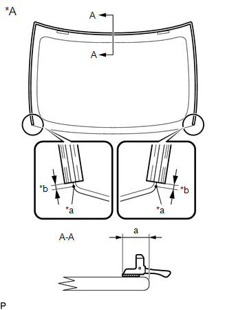
3. INSTALL BACK WINDOW OUTSIDE MOULDING
(a) Using a brush or sponge, coat the installation area of a new back window outside moulding with glass primer.
NOTICE:
- Do not apply too much glass primer.
- Allow the glass primer to dry for 3 minutes or more.
- Throw away any leftover glass primer.
HINT:
If an area other than specified is coated by accident, wipe off the glass primer with a clean piece of cloth before it dries.
| (b) Install the new back window outside moulding to the back wind glass as shown in the illustration. Standard Dimension:
|
|
4. INSTALL BACK WINDOW GLASS ADHESIVE DAM
(a) Using a brush or sponge, coat the installation area of a new back window glass adhesive dam with glass primer.
NOTICE:
- Do not apply too much glass primer.
- Allow the glass primer to dry for 3 minutes or more.
- Throw away any leftover glass primer.
HINT:
If an area other than specified is coated by accident, wipe off the glass primer with a clean piece of cloth before it dries.
(b) Install a new back window glass adhesive dam to the back window glass as shown in the illustration.
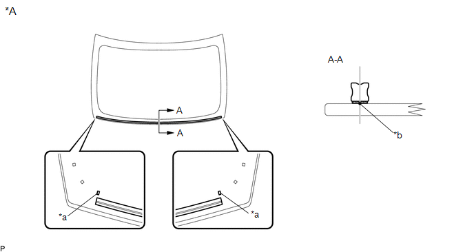
| *A | Back Side | - | - |
| *a | Ceramic Notch | *b | Back Window Glass Adhesive Dam Positioning Center |
5. INSTALL BACK WINDOW GLASS SUB-ASSEMBLY
| (a) Position the back window glass sub-assembly. (1) Using suction cups, place the back window glass sub-assembly in the correct position. (2) Check that the whole contact surface of the back window glass sub-assembly rim is perfectly even. (3) Align the matchmarks on the back window glass sub-assembly and vehicle body. NOTICE: Check that the back window glass stoppers are engaged to the vehicle body correctly. (4) Remove the back window glass sub-assembly. |
|
.png)
(b) Using a brush, coat the installation surface on the vehicle body with body primer.
NOTICE:
- Do not coat the adhesive with body primer.
- Do not apply too much body primer.
- Allow the body primer to dry for 3 minutes or more.
- Throw away any leftover body primer.
HINT:
If an area other than specified is coated by accident, wipe off the body primer with a clean piece of cloth before it dries.
(c) Using a brush or sponge, coat the adhesive application area with glass primer.
| *A | Back Side | - | - |
| *a | Adhesive Application Area | *b | Ceramic Notch |
.png) | Glass Primer | - | - |
Standard Dimension:
| Area | Dimension |
|---|---|
| a | 8.0 mm (0.315 in.) or more |
| b | 8.0 mm (0.315 in.) or more |
| c | 8.0 mm (0.315 in.) or more |
NOTICE:
- Do not apply too much glass primer.
- Allow the glass primer to dry for 3 minutes or more.
- Throw away any leftover glass primer.
HINT:
- Apply glass primer on to the ceramic notches.
- If an area other than specified is coated by accident, wipe off the glass primer with a clean piece of cloth before it dries.
(d) Apply adhesive to the back window glass sub-assembly.
Adhesive:
Toyota Genuine Windshield Glass Adhesive (High modulus Type) or Equivalent
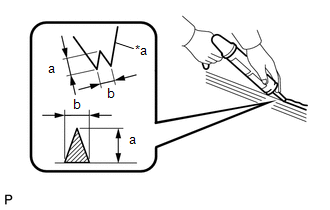
| (1) Cut off the tip of the cartridge nozzle as shown in the illustration. Standard Dimension:
|
|
(2) Load the sealer gun with the cartridge.
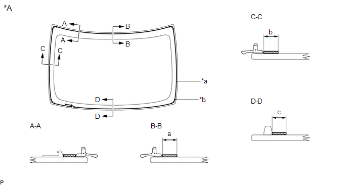
(3) Apply adhesive to the back window glass sub-assembly as shown in the illustration.
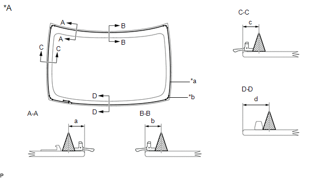
| *A | Back Side | - | - |
| *a | Adhesive Positioning Center | *b | Ceramic Notch |
| | Adhesive | - | - |
Standard Dimension:
| Area | Dimension |
|---|---|
| a | 10.0 mm (0.394 in.) |
| b | 10.0 mm (0.394 in.) |
| c | 10.0 mm (0.394 in.) |
| d | 16.7 mm (0.657 in.) |
HINT:
Apply adhesive to the ceramic notches.
(e) Install the back window glass sub-assembly.
| (1) Using suction cups, position the back window glass sub-assembly so that the matchmarks are aligned, and press it in gently along the rim. NOTICE:
|
|
(2) Lightly press the outer surface of the back window glass sub-assembly to ensure that the back window glass is securely fit to the vehicle body.
HINT:
Press the glass with a force of 98 N (10 kgf, 22.0 lbf) or more.
(3) Using a scraper, remove any excess or protruding adhesive.
(4) Hold the back window glass sub-assembly using protective tape until the applied adhesive becomes hard.
HINT:
Follow the instructions supplied by the adhesive manufacturer or in the corresponding instruction manual for the minimum amount of time necessary to wait before driving the vehicle.
(f) Connect each connector.
6. INSPECT FOR LEAK
(a) After the adhesive has hardened, apply water from the outside of the vehicle. Check that no water leaks into the cabin.
(b) If water leaks into the cabin, allow the water to dry and add adhesive.
(c) Remove the protective tape.
7. INSTALL PACKAGE TRAY TRIM PANEL ASSEMBLY (w/o Rear Sunshade)
Click here .gif)
8. INSTALL NO. 2 PACKAGE TRAY TRIM PANEL ASSEMBLY (w/ Rear Sunshade)
Click here
9. INSTALL PACKAGE TRAY TRIM PANEL ASSEMBLY (w/ Rear Sunshade)
Click here
10. INSTALL REAR SEAT SHOULDER BELT COVER
Click here
11. INSTALL CENTER STOP LIGHT SET
Click here
12. CONNECT REAR SEAT OUTER BELT ASSEMBLY LH
Click here
13. CONNECT REAR SEAT OUTER BELT ASSEMBLY RH
HINT:
Use the same procedure as for the LH side.
14. INSTALL ROOF HEADLINING ASSEMBLY
Click here
READ NEXT:
 Front Passenger Side Power Window Switch
ComponentsCOMPONENTS ILLUSTRATION *1 POWER WINDOW REGULATOR SWITCH ASSEMBLY *2 POWER WINDOW REGULATOR SWITCH ASSEMBLY WITH FRONT DOOR UPPER ARMREST BASE PANEL RemovalREMOVAL PROCEDURE 1
Precaution
PRECAUTION PRECAUTION FOR DISCONNECTING CABLE FROM NEGATIVE BATTERY TERMINAL NOTICE: When disconnecting the cable from the negative (-) battery terminal, initialize the following systems after the cab
SEE MORE:
Parts Location
PARTS LOCATION ILLUSTRATION *1 FRONT CORNER ULTRASONIC SENSOR RH *2 FRONT CENTER ULTRASONIC SENSOR RH *3 FRONT CENTER ULTRASONIC SENSOR LH *4 FRONT CORNER ULTRASONIC SENSOR LH *5 REAR CORNER ULTRASONIC SENSOR RH *6 REAR CENTER ULTRASONIC SENSOR RH *7 REAR CENTER U
Freeze Frame Data
FREEZE FRAME DATA DESCRIPTION (a) Whenever a road sign assist system DTC is stored, the forward recognition camera stores the current vehicle state (ECU and sensor information) as Freeze Frame Data. CHECK FREEZE FRAME DATA (a) Connect the Techstream to the DLC3. (b) Turn the power switch on (IG). (c
