Lexus ES: Front Passenger Side Power Window Switch
Components
COMPONENTS
ILLUSTRATION
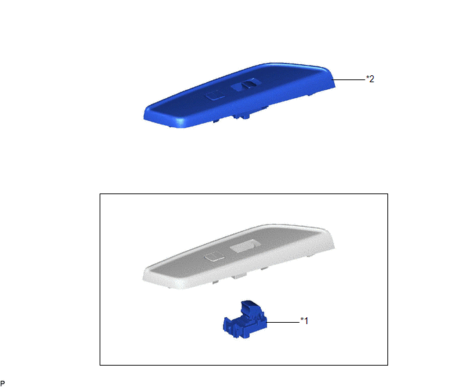
| *1 | POWER WINDOW REGULATOR SWITCH ASSEMBLY | *2 | POWER WINDOW REGULATOR SWITCH ASSEMBLY WITH FRONT DOOR UPPER ARMREST BASE PANEL |
Removal
REMOVAL
PROCEDURE
1. REMOVE POWER WINDOW REGULATOR SWITCH ASSEMBLY WITH FRONT DOOR UPPER ARMREST BASE PANEL
Click here .gif)
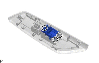
2. REMOVE POWER WINDOW REGULATOR SWITCH ASSEMBLY
| (a) Disengage the 3 claws to remove the power window regulator switch assembly. |
|
Inspection
INSPECTION
PROCEDURE
1. INSPECT POWER WINDOW REGULATOR SWITCH ASSEMBLY
| (a) Check the switch function. (1) Measure the resistance according to the value(s) in the table below. Standard Resistance:
If the result is not as specified, replace the power window regulator switch assembly. |
|
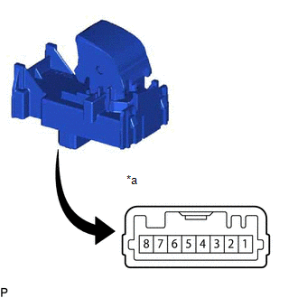
(b) Check that the LED illuminates.
(1) Apply auxiliary battery voltage to the power window regulator switch assembly and check that the LED illuminates.
OK:
| Battery Connection | Specified Condition |
|---|---|
| Auxiliary battery positive (+) → 2 Auxiliary battery negative (-) → 7 | LED illuminates |
If the result is not as specified, replace the power window regulator switch assembly.
READ NEXT:
 Precaution
PRECAUTION PRECAUTION FOR DISCONNECTING CABLE FROM NEGATIVE BATTERY TERMINAL NOTICE: When disconnecting the cable from the negative (-) battery terminal, initialize the following systems after the cab
Parts Location
PARTS LOCATION ILLUSTRATION *1 MAIN BODY ECU (MULTIPLEX NETWORK BODY ECU) *2 COMBINATION METER ASSEMBLY *3 DLC3 *4 CERTIFICATION ECU (SMART KEY ECU ASSEMBLY) *5 INSTRUMENT PA
SEE MORE:
Installation
INSTALLATION
PROCEDURE
1. INSTALL V-RIBBED BELT
HINT:
When reusing the V-ribbed belt, check the ribs and back of the V-ribbed belt
for wear and cracks. If wear or a crack that reaches the core (at more than 1 point)
is found, replace the V-ribbed belt.
(a) Set the V-ribbed belt o
Transmission (Shaft) Mechanical Linkage Failure (P314779)
DTC SUMMARY Refer to the DTC summary for DTC P1C7779. Click here DESCRIPTION Refer to the description for DTC P1C7779. Click here DTC No. Detection Item DTC Detection Condition Trouble Area MIL Warning Indicate P314779 Transmission (Shaft) Mechanical Linkage Failure Drive fo
