Lexus ES: Power Trunk Lid does not Operate Using Outside Switch
DESCRIPTION
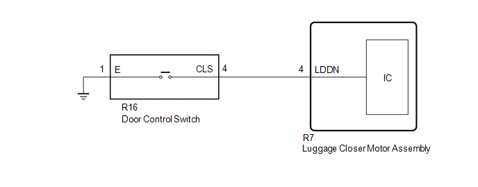
The door control switch signal is sent to the luggage closer motor assembly.
If the power trunk lid does not operate using the door control switch, a door control switch circuit malfunction is a possible cause.
WIRING DIAGRAM
CAUTION / NOTICE / HINT
NOTICE:
If the luggage closer motor assembly has been removed and installed or replaced, or if any of the connectors has been disconnected, initialize the power trunk lid system.
Click here .gif)
PROCEDURE
| 1. | READ VALUE USING TECHSTREAM |
(a) Connect the TECHSTREAM to the DLC3.
(b) Turn the engine switch on (IG).
(c) Turn the TECHSTREAM on.
(d) Enter the following menus: Body Electrical / Back Door / Data List.
(e) Read the Data List according to the display on the TECHSTREAM.
Body Electrical > Back Door > Data List| Tester Display | Measurement Item | Range | Normal Condition | Diagnostic Note |
|---|---|---|---|---|
| PBD Close SW | Door control switch signal | OFF or ON | OFF: Door control switch off ON: Door control switch on | - |
| Tester Display |
|---|
| PBD Close SW |
OK:
The Data List item changes according to the operation of the door control switch.
| OK | .gif) | REPLACE LUGGAGE CLOSER MOTOR ASSEMBLY |
|
.gif)
| 2. | INSPECT DOOR CONTROL SWITCH |
(a) Remove the door control switch.
Click here
(b) Inspect the door control switch.
Click here
| NG | | REPLACE DOOR CONTROL SWITCH |
|
| 3. | CHECK HARNESS AND CONNECTOR (DOOR CONTROL SWITCH - LUGGAGE CLOSER MOTOR ASSEMBLY) |
(a) Disconnect the R7 luggage closer motor assembly connector.
(b) Measure the resistance according to the value(s) in the table below.
| Tester Connection | Condition | Specified Condition |
|---|---|---|
| R16-4 (CSW) - R7-4 (LDDN) | Always | Below 1 Ω |
| R16-1 (E) - Body ground | Always | Below 1 Ω |
| R16-4 (CSW) or R7-4 (LDDN) - Body ground | Always | 10 kΩ or higher |
| OK | | REPLACE LUGGAGE CLOSER MOTOR ASSEMBLY |
| NG | | REPAIR OR REPLACE HARNESS OR CONNECTOR |
READ NEXT:
 Precaution
PRECAUTION PRECAUTION FOR DISCONNECTING CABLE FROM NEGATIVE AUXILIARY BATTERY TERMINAL NOTICE: When disconnecting the cable from the negative (-) auxiliary battery terminal, initialize the following s
Parts Location
PARTS LOCATION ILLUSTRATION *1 LUGGAGE DOOR OPENING CANCEL SWITCH ASSEMBLY *2 TRUNK AND FUEL SWITCH ASSEMBLY *3 LUGGAGE COMPARTMENT DOOR OPENING SWITCH *4 DLC3 *5 MAIN BODY E
SEE MORE:
On-vehicle Inspection
ON-VEHICLE INSPECTION PROCEDURE 1. INSPECT THROTTLE BODY WITH MOTOR ASSEMBLY (a) Before cleaning, or after cleaning the throttle body with motor assembly and installing it to the vehicle, turn the engine switch on (IG) without operating the accelerator pedal sensor assembly. NOTICE: If the accelerat
Main Body ECU Vehicle Information Reading/Writing Process Malfunction (B15F6)
DESCRIPTION This DTC is stored when items controlled by the main body ECU (multiplex network body ECU) cannot be customized via the navigation system vehicle customization screen. HINT: The main body ECU (multiplex network body ECU) controls the items for the following systems that are customizable
