Lexus ES: Removal
REMOVAL
CAUTION / NOTICE / HINT
The necessary procedures (adjustment, calibration, initialization or registration) that must be performed after parts are removed and installed, or replaced during sliding roof housing removal/installation are shown below.
Necessary Procedure After Parts Removed/Installed/Replaced (for Gasoline Model)| Replaced Part or Performed Procedure | Necessary Procedure | Effect/Inoperative Function When Necessary Procedures are not Performed | Link |
|---|---|---|---|
|
*: When performing learning using the Techstream.
Click here | |||
| Disconnect cable from negative (-) battery terminal | Perform steering sensor zero point calibration | Lane Control System (for Gasoline Model) | |
| Pre-collision System (for Gasoline Model) | |||
| Parking Support Brake System (for Gasoline Model)* | |||
| Lighting System (for Gasoline Model) | |||
| Memorize steering angle neutral point | Parking Assist Monitor System (for Gasoline Model) | | |
| Panoramic View Monitor System (for Gasoline Model) | | ||
| Initialize power trunk lid system | Power Trunk Lid System (for Gasoline Model) | | |
| Removal/installation of the front passenger seat | Zero point calibration (Occupant Classification System) |
| |
| Steering sensor | Steering angle zero point learning (Initialize parking support brake system) |
| |
| Parking Assist Monitor System (for Gasoline Model) | | |
| Steering angle zero point learning (Initialize panoramic view monitor system) | Panoramic View Monitor System (for Gasoline Model) | | |
| Initialize sliding roof system |
| |
CAUTION:
Some of these service operations affect the SRS airbag system. Read the precautionary notices concerning the SRS airbag system before servicing.
.png)
Click here .gif)
NOTICE:
- After the engine switch is turned off, the radio receiver assembly records various types of memory and settings. As a result, after turning the engine switch off, make sure to wait at least 85 seconds before disconnecting the cable from the negative (-) battery terminal. (for Audio and Visual System)
- After the engine switch is turned off, the radio receiver assembly records various types of memory and settings. As a result, after turning the engine switch off, make sure to wait at least 85 seconds before disconnecting the cable from the negative (-) battery terminal. (for Navigation System)
| Replaced Part or Performed Procedure | Necessary Procedure | Effect/Inoperative Function When Necessary Procedures are not Performed | Link |
|---|---|---|---|
|
*: When performing learning using the Techstream.
Click here | |||
| Disconnect cable from negative (-) auxiliary battery terminal | Perform steering sensor zero point calibration | Lane Control System (for HV Model) | |
| Pre-collision System (for HV Model) | |||
| Parking Support Brake System (for HV Model)* | |||
| Lighting System (for HV Model) | |||
| Memorize steering angle neutral point | Parking Assist Monitor System (for HV Model) | | |
| Panoramic View Monitor System (for HV Model) | | ||
| Initialize power trunk lid system | Power Trunk Lid System (for HV Model) | | |
| Removal/installation of the front passenger seat | Zero point calibration (Occupant classification system) |
| |
| Steering sensor | Steering angle zero point learning (Initialize parking support brake system) |
| |
| Parking Assist Monitor System (for HV Model) | | |
| Steering angle zero point learning (Initialize panoramic view monitor system) | Panoramic View Monitor System (for HV Model) | | |
| Initialize sliding roof system |
| |
CAUTION:
Some of these service operations affect the SRS airbag system. Read the precautionary notices concerning the SRS airbag system before servicing.
Click here
NOTICE:
- After the power switch is turned off, the radio receiver assembly records various types of memory and settings. As a result, after turning the power switch off, make sure to wait at least 85 seconds before disconnecting the cable from the negative (-) auxiliary battery terminal. (for Audio and Visual System)
- After the power switch is turned off, the radio receiver assembly records various types of memory and settings. As a result, after turning the power switch off, make sure to wait at least 85 seconds before disconnecting the cable from the negative (-) auxiliary battery terminal. (for Navigation System)
PROCEDURE
1. REMOVE SLIDING ROOF SIDE GARNISH LH
| (a) Disengage the 4 claws to remove the sliding roof side garnish LH. |
|
2. REMOVE SLIDING ROOF SIDE GARNISH RH
HINT:
Use the same procedure as for the LH side.
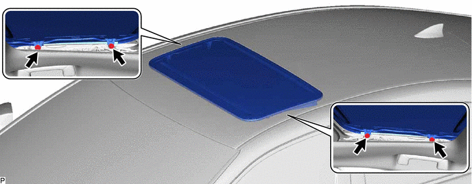
3. REMOVE SLIDING ROOF OR REMOVABLE ROOF PANEL SUB-ASSEMBLY
(a) Move the sliding roof or removable roof panel sub-assembly to the fully closed position.
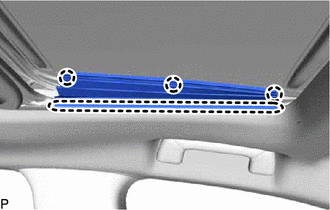
(b) Using a T25 "TORX" socket wrench, remove the 4 screws and sliding roof or removable roof panel sub-assembly.
NOTICE:
To prevent the sliding roof or removable roof panel sub-assembly and sliding roof drive gear sub-assembly from becoming misaligned, move the sliding roof or removable roof panel sub-assembly (sliding roof drive cable sub-assembly) to the fully closed position before removing it.
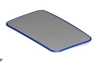
4. REMOVE SLIDING ROOF WEATHERSTRIP
| (a) Remove the sliding roof weatherstrip from the sliding roof panel sub-assembly. |
|
5. REMOVE CURTAIN SHIELD AIRBAG ASSEMBLY LH
Click here
6. REMOVE CURTAIN SHIELD AIRBAG ASSEMBLY RH
HINT:
Use the same procedure as for the LH side.
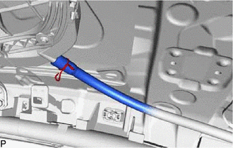
7. DISCONNECT SLIDING ROOF DRAIN HOSE
HINT:
Use the same procedure for all of the sliding roof drain hoses.
| (a) for Clamp Type: (1) Disengage the claw and disconnect the sliding roof drain hose. |
|
| (b) for Clip Type: (1) Expand the clip and disconnect the sliding roof drain hose. |
|
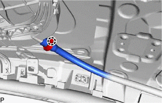
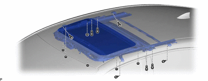
8. REMOVE SLIDING ROOF OR REMOVABLE ROOF HOUSING SUB-ASSEMBLY
(a) Remove the 8 bolts, 6 nuts and sliding roof or removable roof housing sub-assembly.
READ NEXT:
 Disassembly
DISASSEMBLY PROCEDURE 1. REMOVE SLIDING ROOF DRIVE GEAR SUB-ASSEMBLY (a) Remove the bolt. Remove in this Direction (b) Disengage the claw and guide as shown in the illustration to remove the
Reassembly
REASSEMBLY PROCEDURE 1. INSTALL ROOF WIND DEFLECTOR PANEL SUB-ASSEMBLY (a) Move the roof wind deflector panel sub-assembly in the direction indicated by the arrow (1) shown in the illustration to enga
Installation
INSTALLATION PROCEDURE 1. INSTALL SLIDING ROOF OR REMOVABLE ROOF HOUSING SUB-ASSEMBLY (a) Loosen the 4 bolts of the brackets of the sliding roof or removable roof housing sub-assembly. (b) Temporaril
SEE MORE:
Motor/Generator Shutdown Signal (MG Side) Stuck Off (P33BF9F)
DTC SUMMARY MALFUNCTION DESCRIPTION The hybrid vehicle control ECU detects malfunctions which prevent the inverter with converter assembly emergency shutdown circuit (HSDN) from shutting down the hybrid control system. Detection is performed when the power switch is turned on (IG) and during the shu
High Pressure Fuel Pump Circuit Open (P123513)
DESCRIPTION The high-pressure direct injection fuel system consists of a spill control valve, check valve, fuel relief valve, fuel pressure sensor, fuel pump assembly (for high pressure side) and direct fuel injector assemblies. The spill control valve adjusts the return volume of the high-pressure
