Lexus ES: Reassembly
REASSEMBLY
PROCEDURE
1. INSTALL ROOF WIND DEFLECTOR PANEL SUB-ASSEMBLY
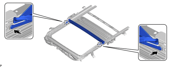
(a) Move the roof wind deflector panel sub-assembly in the direction indicated by the arrow (1) shown in the illustration to engage the 2 guides and install the roof wind deflector panel sub-assembly.
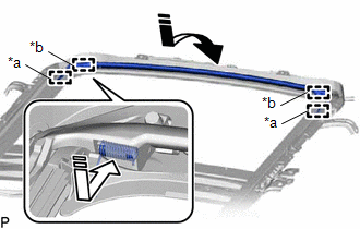
| *a | Guide |
| *b | Spring |
.png) | Install in this Direction (1) |
.png) | Install in this Direction (2) |
(b) Push each spring in the direction indicated by the arrow (2) shown in the illustration to engage the 2 springs.
NOTICE:
Make sure that the springs are securely engaged.
2. INSTALL SLIDING ROOF DRIVE CABLE SUB-ASSEMBLY
NOTICE:
Perform this procedure only when replacement of the sliding roof drive cable sub-assembly is necessary.
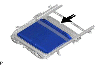
(a) Hold down the roof wind deflector panel sub-assembly.
.png)
.png) | Hold Position |
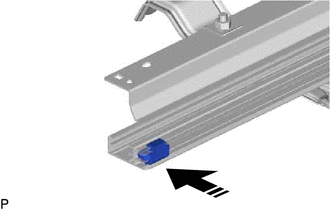
(b) Using a screwdriver, slide the sliding roof drive cable LH as shown in the illustration to install it.
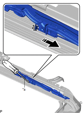
| *a | Protective Tape |
| | Push Position |
| | Install in this Direction |
HINT:
- Tape the screwdriver tip before use.
- Use the same procedure for the RH side.
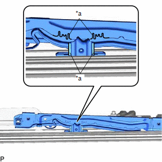
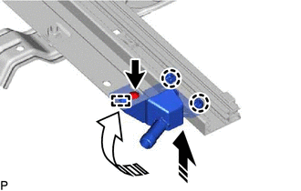
| (c) Adjust Fully Closed Position: (1) Using a screwdriver, slide the sliding roof drive cable LH in either direction and align the alignment marks as shown in the illustration. HINT: Use the same procedure for the RH side. |
|
3. INSTALL REAR ROOF DRIP CHANNEL
(a) Insert the rear roof drip channel into the sliding roof housing sub-assembly as shown in the illustration.
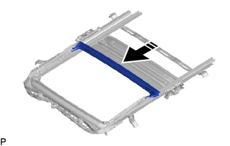
| | Install in this Direction |
(b) Engage the 2 claws as shown in the illustration to install the rear roof drip channel.
| | Install in this Direction | - | - |
4. INSTALL SUNSHADE TRIM SUB-ASSEMBLY
(a) Insert the sunshade trim sub-assembly into the sliding roof housing sub-assembly as shown in the illustration to install it.
| | Install in this Direction |
(b) Install the rear sliding roof sunshade stopper as shown in the illustration.
| | Install in this Direction |
HINT:
Use the same procedure for the RH side.
(c) Move the sliding roof piece sub-assembly LH in the direction indicated by the arrow (1) shown in the illustration to engage the 2 claws.
| | Install in this Direction (1) |
| | Install in this Direction (2) |
HINT:
Use the same procedure for the RH side.
(d) Move the sliding roof piece sub-assembly LH in the direction indicated by the arrow (2) shown in the illustration to engage the guide.
HINT:
Use the same procedure for the RH side.
(e) Install the sliding roof piece sub-assembly LH with the screw.
HINT:
Use the same procedure for the RH side.
5. INSTALL SLIDING ROOF DRIVE GEAR SUB-ASSEMBLY
(a) Apply MP grease to the gear of the sliding roof drive gear sub-assembly.
| (b) Install the sliding roof drive gear sub-assembly with the 2 bolts. Torque: 5.4 N·m {55 kgf·cm, 48 in·lbf} |
|
.png)
(c) Engage the guide and claw as shown in the illustration.
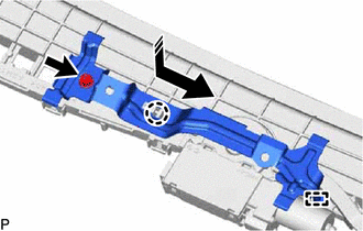
| | Install in this Direction |
(d) Install the map light bracket with the bolt.
Torque:
5.4 N·m {55 kgf·cm, 48 in·lbf}
READ NEXT:
 Installation
INSTALLATION PROCEDURE 1. INSTALL SLIDING ROOF OR REMOVABLE ROOF HOUSING SUB-ASSEMBLY (a) Loosen the 4 bolts of the brackets of the sliding roof or removable roof housing sub-assembly. (b) Temporaril
Sliding Roof Switch Assembly
ComponentsCOMPONENTS ILLUSTRATION *1 MAP LIGHT ASSEMBLY *2 MAP LIGHT SUB-ASSEMBLY *3 ROOF CONSOLE BOX INNER COVER - - ● Non-reusable part - - InspectionINSPECTION
SEE MORE:
Hybrid/EV Battery Current Sensor for Driving Control Voltage Out of Range (P1C9F1C)
DESCRIPTION Refer to the description for DTC P0ABF11. Click here DTC No. Detection Item DTC Detection Condition Trouble Area MIL Warning Indicate P1C9F1C Hybrid/EV Battery Current Sensor for Driving Control Voltage Out of Range The difference between IBA and IB0 exceeds the th
Terminals Of Ecu
TERMINALS OF ECU CHECK INSTRUMENT PANEL JUNCTION BLOCK ASSEMBLY AND MAIN BODY ECU (MULTIPLEX NETWORK BODY ECU) (a) Disconnect the MB main body ECU (multiplex network body ECU) connector. Click here (b) Measure the voltage and resistance according to the value(s) in the table below. HINT: Measure
