Lexus ES: Disassembly
DISASSEMBLY
PROCEDURE
1. REMOVE SLIDING ROOF DRIVE GEAR SUB-ASSEMBLY
(a) Remove the bolt.
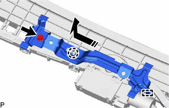
.png) | Remove in this Direction |
(b) Disengage the claw and guide as shown in the illustration to remove the map light bracket.
| (c) Remove the 2 bolts and sliding roof drive gear sub-assembly. |
|
2. REMOVE SUNSHADE TRIM SUB-ASSEMBLY
(a) Remove the screw.
| | Remove in this Direction (1) |
.png) | Remove in this Direction (2) |
HINT:
Use the same procedure for the RH side.
(b) Move the sliding roof piece sub-assembly LH in the direction indicated by the arrow (1) shown in the illustration to disengage the guide.
HINT:
Use the same procedure for the RH side.
(c) Move the sliding roof piece sub-assembly LH in the direction indicated by the arrow (2) shown in the illustration to disengage the 2 claws and remove the sliding roof piece sub-assembly LH.
HINT:
Use the same procedure for the RH side.
(d) Remove the rear sliding roof sunshade stopper as shown in the illustration.
| | Remove in this Direction |
HINT:
Use the same procedure for the RH side.
(e) Slide and remove the sunshade trim sub-assembly as shown in the illustration.
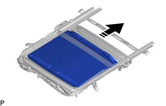
| | Remove in this Direction |
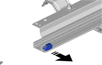
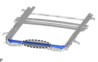
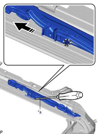
3. REMOVE REAR ROOF DRIP CHANNEL
(a) Using a screwdriver, disengage the 2 claws as shown in the illustration.
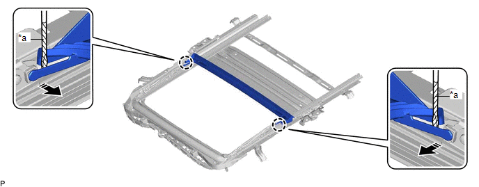
| *a | Protective Tape | - | - |
| | Remove in this Direction | - | - |
HINT:
Tape the screwdriver tip before use.
(b) Slide and remove the rear roof drip channel as shown in the illustration.
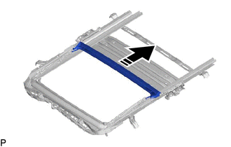
| | Remove in this Direction |
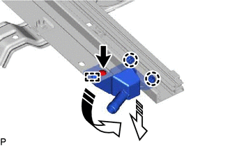
4. REMOVE SLIDING ROOF DRIVE CABLE SUB-ASSEMBLY
NOTICE:
Perform this procedure only when replacement of the sliding roof drive cable sub-assembly is necessary.
(a) Hold down the roof wind deflector panel sub-assembly.
.png) | Hold Position |
(b) Using a screwdriver, slide the sliding roof drive cable LH as shown in the illustration to remove it.
| *a | Protective Tape |
| | Push Position |
| | Remove in this Direction |
HINT:
- Tape the screwdriver tip before use.
- Use the same procedure for the RH side.
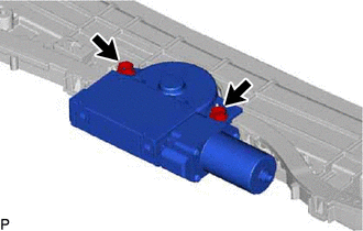
5. REMOVE ROOF WIND DEFLECTOR PANEL SUB-ASSEMBLY
(a) Pull each spring in the direction indicated by the arrow (1) shown in the illustration to disengage the 2 springs.
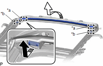
| *a | Spring |
| *b | Guide |
| | Remove in this Direction (1) |
| | Remove in this Direction (2) |
(b) Pull the roof wind deflector panel sub-assembly in the direction indicated by the arrow (2) shown in the illustration to disengage the 2 guides and remove it.
READ NEXT:
 Reassembly
REASSEMBLY PROCEDURE 1. INSTALL ROOF WIND DEFLECTOR PANEL SUB-ASSEMBLY (a) Move the roof wind deflector panel sub-assembly in the direction indicated by the arrow (1) shown in the illustration to enga
Installation
INSTALLATION PROCEDURE 1. INSTALL SLIDING ROOF OR REMOVABLE ROOF HOUSING SUB-ASSEMBLY (a) Loosen the 4 bolts of the brackets of the sliding roof or removable roof housing sub-assembly. (b) Temporaril
Sliding Roof Switch Assembly
ComponentsCOMPONENTS ILLUSTRATION *1 MAP LIGHT ASSEMBLY *2 MAP LIGHT SUB-ASSEMBLY *3 ROOF CONSOLE BOX INNER COVER - - ● Non-reusable part - - InspectionINSPECTION
SEE MORE:
GVIF Disconnected (from EMV/MM Integrated Device to Multi Display) (B1575)
DESCRIPTION The radio receiver assembly and multi-display assembly are connected via video signal (digital) lines. This DTC is stored when a video signal (digital) line is disconnected. DTC No. Detection Item DTC Detection Condition Trouble Area B1575 GVIF Disconnected (from EMV/MM In
Shift Lever Knob
ComponentsCOMPONENTS ILLUSTRATION *1 SHIFT LEVER KNOB SUB-ASSEMBLY - - InstallationINSTALLATION PROCEDURE 1. INSTALL SHIFT LEVER KNOB SUB-ASSEMBLY (a) Install the shift lever knob sub-assembly to the transmission floor shift assembly. (b) Engage the 2 claws to connec
