Lexus ES: Removal
REMOVAL
CAUTION / NOTICE / HINT
The necessary procedures (adjustment, calibration, initialization or registration) that must be performed after parts are removed and installed, or replaced during headlight assembly removal/installation are shown below.
Necessary Procedure After Parts Removed/Installed/Replaced (for HV Model)| Replaced Part or Performed Procedure | Necessary Procedure | Effect/Inoperative Function when Necessary Procedure not Performed | Link |
|---|---|---|---|
| Front bumper assembly |
|
| |
| Front television camera view adjustment | Panoramic View Monitor System (for HV Model) | for Initialization for Calibration | |
| Headlight ECU sub-assembly LH |
| Lighting system (for HV Model) | |
| Replaced Part or Performed Procedure | Necessary Procedure | Effect/Inoperative Function when Necessary Procedure not Performed | Link |
|---|---|---|---|
| Front bumper assembly |
|
| |
| Front television camera view adjustment | Panoramic View Monitor System (for Gasoline Model) | for Initialization for Calibration | |
| Headlight ECU sub-assembly LH |
| Lighting System (for Gasoline Model) | |
HINT:
- Use the same procedure for the RH side and LH side.
- The following procedure is for the LH side.
PROCEDURE
1. REMOVE FRONT BUMPER ASSEMBLY
Click here .gif)
2. REMOVE COWL TOP PANEL INSULATOR
Click here
3. REMOVE FRONT FENDER SPLASH SHIELD SUB-ASSEMBLY
Click here
4. REMOVE HEADLIGHT ASSEMBLY
(a) Apply protective tape around the headlight assembly as shown in the illustration.
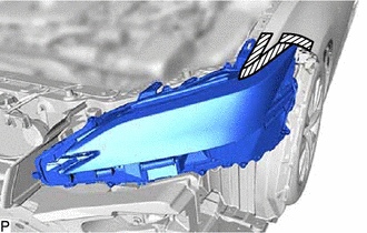
.png) | Protective Tape |
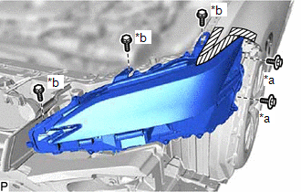
| (b) Remove the 2 bolts and 3 screws. |
|
(c) Disengage the 2 guides to separate the headlight assembly as shown in the illustration.
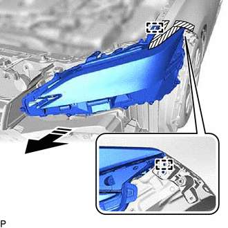
.png) | Remove in this Direction |
(d) Disengage the claw, pull down the connector lock lever as shown in the illustration and disconnect the connector to remove the headlight assembly.
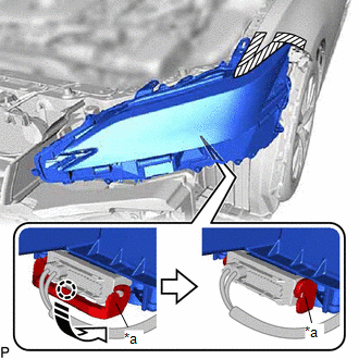
| *a | Connector Lock Lever |
| | Disconnect in this Direction |
READ NEXT:
 Disassembly
DISASSEMBLY CAUTION / NOTICE / HINT HINT:
Use the same procedure for the RH side and LH side.
The following procedure is for the LH side.
PROCEDURE 1. REMOVE HEADLIGHT ECU SUB-ASSEMBLY Click h
Adjustment
ADJUSTMENT CAUTION / NOTICE / HINT HINT:
Use the same procedure for the RH side and LH side.
The following procedure is for the LH side.
PROCEDURE 1. PREPARE VEHICLE FOR HEADLIGHT AIM ADJUSTME
Reassembly
REASSEMBLY CAUTION / NOTICE / HINT HINT:
Use the same procedure for the RH side and LH side.
The following procedure is for the LH side.
PROCEDURE 1. INSTALL HEADLIGHT SEAL (for TMC Made) HINT
SEE MORE:
System Voltage (BATT) Circuit Short to Ground or Open (P056014)
DESCRIPTION Auxiliary battery power is supplied to the AM terminal of the battery ECU assembly in order to store DTCs and freeze frame data. Even if the power switch is turned off, back-up power is supplied. DTC No. Detection Item DTC Detection Condition Trouble Area MIL Warning Indicat
Lost Communication with Hybrid/EV Powertrain Control Module Missing Message (U029387)
DESCRIPTION The battery ECU assembly transmits and receives signals via CAN communication to and from the hybrid vehicle control ECU. DTC No. Detection Item DTC Detection Condition Trouble Area MIL Warning Indicate U029387 Lost Communication with Hybrid/EV Powertrain Control Modul
