Lexus ES: Reassembly
REASSEMBLY
CAUTION / NOTICE / HINT
HINT:
- Use the same procedure for the RH side and LH side.
- The following procedure is for the LH side.
PROCEDURE
1. INSTALL HEADLIGHT SEAL (for TMC Made)
HINT:
Perform this procedure only when replacement of the headlight seal is necessary.
(a) Clean the installation area of the headlight seal shown in the illustration.
NOTICE:
Remove any remaining double-sided tape, and then clean the area with non-residue solvent.
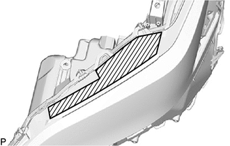
.png) | Cleaning Area |
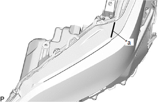
(b) Remove approximately 30 mm (1.18 in.) of the release paper from a new headlight seal.
| (c) Align the exposed end of the headlight seal with the line. |
|
(d) Gradually remove the release paper and temporarily install the headlight seal while keeping it aligned with the curve of the headlight unit assembly.
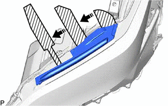
| | Release Paper |
.png) | Remove in this Direction |
(e) Press the entire length of the headlight seal to install it.
NOTICE:
When pressing, do not slide your finger, as doing so may stretch the part.
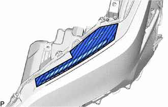
| | Press Area |
2. INSTALL HEADLIGHT UNIT ASSEMBLY
3. INSTALL NO. 2 HEADLIGHT FITTING RIM
| (a) Engage the 2 guides. |
|
.png)
(b) Install the No. 2 headlight fitting rim with the 2 screws.
4. INSTALL HEADLIGHT RIM
| (a) Engage the 2 guides. |
|
.png)
(b) Install the headlight rim with the screw.
5. INSTALL HEADLIGHT GASKET
Click here .gif)
6. INSTALL HEADLIGHT ECU SUB-ASSEMBLY
Click here
READ NEXT:
 Installation
INSTALLATION CAUTION / NOTICE / HINT HINT:
Use the same procedure for the RH side and LH side.
The following procedure is for the LH side.
PROCEDURE 1. INSTALL HEADLIGHT ASSEMBLY (a) Connect t
Repair
REPAIR CAUTION / NOTICE / HINT HINT:
Use the same procedure for the RH side and LH side.
The following procedure is for the LH side.
If the installation area of the headlight assembly is damage
SEE MORE:
Left Front Wheel Speed Sensor Circuit Voltage Out of Range (C05001C)
DESCRIPTION Refer to DTC C050012 Click here DTC No. Detection Item DTC Detection Condition Trouble Area C05001C Left Front Wheel Speed Sensor Circuit Voltage Out of Range
When the vehicle is being driven in a straight line at a speed of 20 km/h (12 mph) or more and VSC/TRAC has
Installation
INSTALLATION PROCEDURE 1. INSTALL TIMING CHAIN COVER ASSEMBLY (a) Clean the contact surfaces of the engine assembly, and confirm that no oil, moisture, or other foreign matter is on the surfaces. *a Engine Assembly Side *b Timing Chain Cover Assembly Side Clean - - NOTICE: Be
