Lexus ES: Removal
REMOVAL
CAUTION / NOTICE / HINT
The necessary procedures (adjustment, calibration, initialization, or registration) that must be performed after parts are removed and installed, or replaced during grille shutter removal/installation are shown below.
Necessary Procedure After Parts Removed/Installed/Replaced| Replaced Part or Performed Procedure | Necessary Procedure | Effect/Inoperative Function when Necessary Procedure not Performed | Link |
|---|---|---|---|
| Front television camera view adjustment | Panoramic View Monitor System (for HV Model) | |
| Front bumper assembly |
|
| |
| Change grille shutter control mode and/or perform initialization | Grille Shutter system | |
PROCEDURE
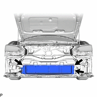
1. REMOVE FRONT BUMPER ASSEMBLY
Click here .gif)
2. REMOVE FRONT RADIATOR SIDE AIR GUIDE PLATE LH
| (a) Disengage the 2 claws to remove the front radiator side air guide plate LH. |
|
3. REMOVE FRONT RADIATOR SIDE AIR GUIDE PLATE RH
| (a) Disengage the 2 claws to remove the front radiator side air guide plate RH. |
|
4. REMOVE THERMISTOR ASSEMBLY
Click here
5. REMOVE RADIATOR SHUTTER SUB-ASSEMBLY
| (a) Disconnect the connector. |
|
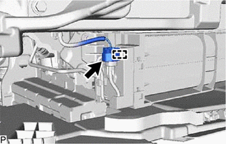
(b) Disengage the clamp.
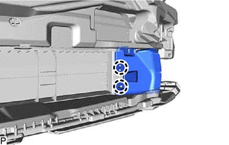
| (c) Remove the 3 bolts. |
|
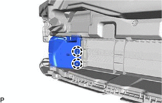
(d) Disengage the 2 guides to remove the radiator shutter sub-assembly as shown in the illustration.
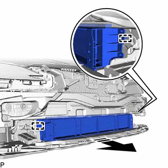
.png) | Remove in this Direction |
READ NEXT:
 Disassembly
DISASSEMBLY PROCEDURE 1. REMOVE MOTOR COVER (a) Disconnect the connector. (b) Disengage the 2 clamps. (c) Disengage the 4 claws to remove the motor cover as shown in the illustration.
Reassembly
REASSEMBLY PROCEDURE 1. INSTALL NO. 2 RADIATOR GRILLE SEAL HINT: When installing the No. 2 radiator grille seal, heat the radiator shutter using a heat light. Heating Temperature Item Temperature
Installation
INSTALLATION PROCEDURE 1. INSTALL RADIATOR SHUTTER SUB-ASSEMBLY (a) Engage the 2 guides as shown in the illustration. Install in this Direction (b) Install the radiator shutter sub-assembly
SEE MORE:
Parts Location
PARTS LOCATION ILLUSTRATION *1 PARK/NEUTRAL POSITION SWITCH ASSEMBLY *2 SIDE TURN SIGNAL LIGHT ASSEMBLY LH *3 SIDE TURN SIGNAL LIGHT ASSEMBLY RH *4 HEADLIGHT ASSEMBLY LH - HEADLIGHT ECU SUB-ASSEMBLY LH - HEADLIGHT UNIT ASSEMBLY LH (for TMC Made) - HEADLIGHT CORD LH (for Bulb Type
Terminals Of Ecu
TERMINALS OF ECU NOTICE:
After turning the power switch off, waiting time may be required before disconnecting the cable from the negative (-) auxiliary battery terminal. Therefore, make sure to read the disconnecting the cable from the negative (-) auxiliary battery terminal notices before proce
