Lexus ES: Removal
REMOVAL
CAUTION / NOTICE / HINT
The necessary procedures (adjustment, calibration, initialization, or registration) that must be performed after parts are removed and installed, or replaced during black out tape removal/installation are shown below.
Necessary Procedure After Parts Removed/Installed/Replaced (for HV Model)| Replaced Part or Performed Procedure | Necessary Procedure | Effect/Inoperative Function When Necessary Procedures are not Performed | Link |
|---|---|---|---|
|
*: When performing learning using the Techstream.
Click here | |||
| Disconnect cable from negative auxiliary battery terminal | Perform steering sensor zero point calibration | Lane Control System | |
| Pre-collision System | |||
| Parking Support Brake System* | |||
| Lighting System | |||
| Memorize steering angle neutral point | Parking Assist Monitor System | | |
| Panoramic View Monitor System | | ||
| Initialize power trunk lid system | Power Trunk Lid System | | |
| Initialize power window control system |
| |
NOTICE:
- After the power switch is turned off, the radio receiver assembly records various types of memory and settings. As a result, after turning the power switch off, make sure to wait at least 85 seconds before disconnecting the cable from the negative (-) auxiliary battery terminal. (for Audio and Visual System)
- After the power switch is turned off, the radio receiver assembly records various types of memory and settings. As a result, after turning the power switch off, make sure to wait at least 85 seconds before disconnecting the cable from the negative (-) auxiliary battery terminal. (for Navigation System)
| Replaced Part or Performed Procedure | Necessary Procedure | Effect/Inoperative Function When Necessary Procedures are not Performed | Link |
|---|---|---|---|
|
*: When performing learning using the Techstream.
Click here | |||
| Disconnect cable from negative battery terminal | Perform steering sensor zero point calibration | Lane Control System | |
| Pre-collision System | |||
| Parking Support Brake System* | |||
| Lighting System | |||
| Memorize steering angle neutral point | Parking Assist Monitor System | | |
| Panoramic View Monitor System | | ||
| Initialize power trunk lid system | Power Trunk Lid System | | |
| Initialize power window control system |
| |
NOTICE:
- After the engine switch is turned off, the radio receiver assembly records various types of memory and settings. As a result, after turning the engine switch off, make sure to wait at least 85 seconds before disconnecting the cable from the negative (-) battery terminal. (for Audio and Visual System)
- After the engine switch is turned off, the radio receiver assembly records various types of memory and settings. As a result, after turning the engine switch off, make sure to wait at least 85 seconds before disconnecting the cable from the negative (-) battery terminal. (for Navigation System)
HINT:
- Use the same procedure for the RH side and LH side.
- The following procedure is for the LH side.
PROCEDURE
1. PRECAUTION
NOTICE:
After turning the engine switch (for Gasoline Model) or power switch (for HV Model) off, waiting time may be required before disconnecting the cable from the negative (-) auxiliary battery terminal. Therefore, make sure to read the disconnecting the cable from the negative (-) auxiliary battery terminal notices before proceeding with work.
2. DISCONNECT CABLE FROM NEGATIVE AUXILIARY BATTERY TERMINAL
for 2GR-FKS:
Click here .gif)
for A25A-FXS:
Click here
3. REMOVE NO. 2 DOOR TRIM PAD
Click here
4. REMOVE MULTIPLEX NETWORK MASTER SWITCH ASSEMBLY WITH FRONT DOOR UPPER ARMREST BASE PANEL (for Driver Side)
Click here
5. REMOVE POWER WINDOW REGULATOR SWITCH ASSEMBLY WITH FRONT DOOR UPPER ARMREST BASE PANEL (for Front Passenger Side)
Click here
6. REMOVE COURTESY LIGHT ASSEMBLY
Click here
7. REMOVE FRONT DOOR TRIM BOARD SUB-ASSEMBLY
Click here
8. REMOVE FRONT DOOR LOWER FRAME BRACKET GARNISH
Click here
9. REMOVE FRONT DOOR TRIM BRACKET
Click here
10. REMOVE FRONT DOOR SERVICE HOLE COVER
Click here
11. REMOVE FRONT DOOR VENT SEAL
Click here
12. REMOVE FRONT DOOR PANEL PROTECTOR
Click here
13. REMOVE FRONT DOOR GLASS SUB-ASSEMBLY
Click here
14. REMOVE FRONT DOOR GLASS RUN
Click here
15. REMOVE FRONT DOOR CHECK ASSEMBLY
Click here
16. REMOVE DOOR UPPER FRAME GARNISH
Click here
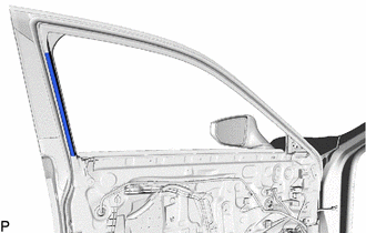
17. REMOVE FRONT DOOR WEATHERSTRIP
Click here
18. REMOVE FRONT DOOR REAR INNER BLACK OUT TAPE
HINT:
When removing the front door rear inner black out tape, heat the vehicle body and front door rear inner black out tape using a heat light.
Heating Temperature| Item | Temperature |
|---|---|
| Front Door Rear Inner Black Out Tape and Vehicle Body | 40 to 60°C (104 to 140°F) |
CAUTION:
- Do not touch the heat light and heated parts, touching the heat light may result in burns.
- Touching heated parts for a long time may result in burns.
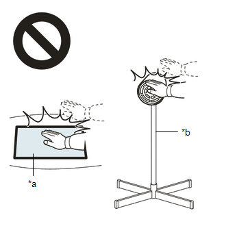
| *a | Heated Part |
| *b | Heat Light |
NOTICE:
Do not heat the vehicle body excessively.
(a) Using a heat light, heat the front door rear inner black out tape and vehicle body.
| (b) Pull back on one of the ends of the front door rear inner black out tape to remove it. HINT: When pulling on the front door rear inner black out tape, pull it parallel to the vehicle body. |
|
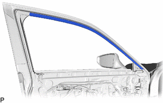
19. REMOVE FRONT INNER BLACK OUT TAPE
HINT:
When removing the front inner black out tape, heat the vehicle body and front inner black out tape using a heat light.
Heating Temperature| Item | Temperature |
|---|---|
| Front Inner Black Out Tape and Vehicle Body | 40 to 60°C (104 to 140°F) |
CAUTION:
- Do not touch the heat light and heated parts, touching the heat light may result in burns.
- Touching heated parts for a long time may result in burns.
| *a | Heated Part |
| *b | Heat Light |
NOTICE:
Do not heat the vehicle body excessively.
(a) Using a heat light, heat the front inner black out tape and vehicle body.
| (b) Pull back on one of the ends of the front inner black out tape to remove it. HINT: When pulling on the front inner black out tape, pull it parallel to the vehicle body. |
|
READ NEXT:
 Installation
INSTALLATION CAUTION / NOTICE / HINT HINT:
Use the same procedure for the RH side and LH side.
The following procedure is for the LH side.
PROCEDURE 1. PRECAUTION NOTICE: After turning the eng
Components
COMPONENTS ILLUSTRATION *1 COURTESY LIGHT ASSEMBLY *2 REAR DOOR TRIM BOARD SUB-ASSEMBLY *3 REAR DOOR UPPER TRIM PAD *4 REAR POWER WINDOW REGULATOR SWITCH ASSEMBLY WITH REAR DOOR UP
SEE MORE:
Replacement
REPLACEMENT PROCEDURE 1. REPLACE INTAKE VALVE GUIDE BUSH (a) Heat the cylinder head sub-assembly to between 80 and 100°C (176 and 212°F). (b) Place the cylinder head sub-assembly on wooden blocks. CAUTION: Be sure to wear protective gloves. (c) Using SST and a hammer, tap out the intake valve g
Camshaft Position Sensor "B" Bank 1 Circuit Short to Ground (P036511,P036515)
DESCRIPTION The camshaft position sensor (for exhaust camshaft) (EV1 signal) consists of a magnet and MRE (Magneto Resistance Element). The exhaust camshaft has a timing rotor for the camshaft position sensor. When the exhaust camshaft rotates, changes occur in the air gaps between the timing rotor
