Lexus ES: Replacement
REPLACEMENT
PROCEDURE
1. REPLACE INTAKE VALVE GUIDE BUSH
(a) Heat the cylinder head sub-assembly to between 80 and 100°C (176 and 212°F).
(b) Place the cylinder head sub-assembly on wooden blocks.
CAUTION:
Be sure to wear protective gloves.
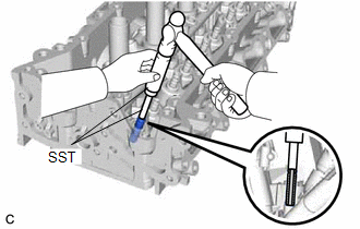
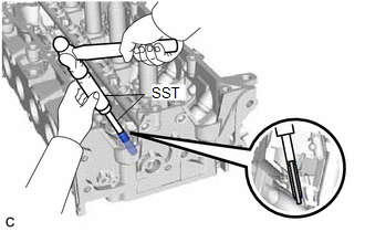
| (c) Using SST and a hammer, tap out the intake valve guide bush. SST: 09201-01055 SST: 09950-70010 09951-07100 |
|
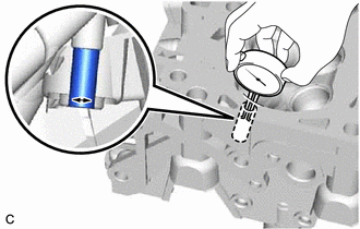
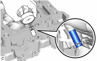
| (d) Using a caliper gauge, measure the intake valve guide bush bore diameter of the cylinder head sub-assembly. Standard Intake Valve Guide Bush Bore Diameter: 10.285 to 10.306 mm (0.405 to 0.406 in.) New Guide Bush Selection Chart:
Standard Bush Length: 41.3 to 41.7 mm (1.63 to 1.64 in.) HINT:
|
|
(e) Heat the cylinder head sub-assembly to between 80 and 100°C (176 and 212°F).
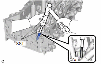
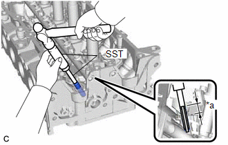
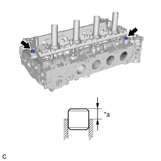
| (f) Using SST and a hammer, tap in the selected intake valve guide bush. SST: 09201-10000 09201-01050 SST: 09950-70010 09951-07100 Standard Protrusion Height: 17.75 to 17.95 mm (0.699 to 0.707 in.) |
|
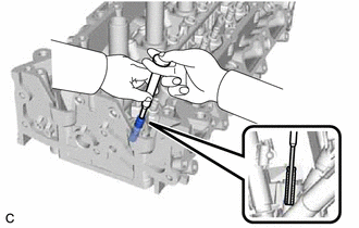
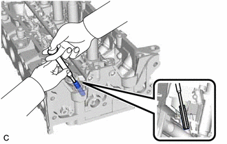
| (g) Using a sharp 5.5 mm reamer, ream the intake valve guide bush to obtain the standard oil clearance. Standard Oil Clearance: 0.025 to 0.060 mm (0.000984 to 0.00236 in.) |
|
2. REPLACE EXHAUST VALVE GUIDE BUSH
(a) Heat the cylinder head sub-assembly to between 80 and 100°C (176 and 212°F).
(b) Place the cylinder head sub-assembly on wooden blocks.
CAUTION:
Be sure to wear protective gloves.
| (c) Using SST and a hammer, tap out the exhaust valve guide bush. SST: 09201-01055 SST: 09950-70010 09951-07100 |
|
| (d) Using a caliper gauge, measure the exhaust valve guide bush bore diameter of the cylinder head sub-assembly. Standard Exhaust Valve Guide Bush Bore Diameter: 10.285 to 10.306 mm (0.405 to 0.406 in.) New Guide Bush Selection Chart:
Standard Bush Length: 43.3 to 43.7 mm (1.70 to 1.72 in.) HINT:
|
|
(e) Heat the cylinder head sub-assembly to between 80 and 100°C (176 and 212°F).
| (f) Using SST and a hammer, tap in the selected exhaust valve guide bush. SST: 09201-10000 09201-01050 SST: 09950-70010 09951-07100 Standard Protrusion Height: 17.75 to 17.95 mm (0.699 to 0.707 in.) |
|
| (g) Using a sharp 5.5 mm reamer, ream the exhaust valve guide bush to obtain the standard oil clearance. Standard Oil Clearance: 0.030 to 0.065 mm (0.00118 to 0.00256 in.) |
|
3. REPLACE RING PIN
NOTICE:
It is not necessary to remove the ring pins unless they are being replaced.
(a) Remove the 2 ring pins.
| (b) Using a plastic hammer, tap in 2 new ring pins to the cylinder head sub-assembly. Standard Protrusion Height: 6.5 to 7.5 mm (0.256 to 0.295 in.) |
|
READ NEXT:
 Reassembly
REASSEMBLY PROCEDURE 1. INSTALL SPARK PLUG TUBE HINT: When using a new cylinder head sub-assembly, the spark plug tubes must be replaced. (a) Apply adhesive to a new spark plug tube as shown in the
Repair
REPAIR PROCEDURE 1. REPAIR EXHAUST VALVE SEAT NOTICE:
While repairing the exhaust valve seat, make sure to constantly check the valve seat width and valve seating position.
Release the cutter gra
Drive Belt
ComponentsCOMPONENTS ILLUSTRATION *1 NO. 2 ENGINE UNDER COVER ASSEMBLY *2 V-RIBBED BELT *3 FRONT WHEEL OPENING EXTENSION PAD LH *4 FRONT WHEEL OPENING EXTENSION PAD RH *5 NO
SEE MORE:
Cooling Fan Circuit
DESCRIPTION The ECM calculates an appropriate cooling fan speed based on the engine coolant temperature, air conditioning switch status, refrigerant pressure, engine speed and vehicle speed, and sends a signal to the cooling fan ECU (fan with motor assembly). The cooling fan ECU (fan with motor asse
Installation
INSTALLATION PROCEDURE 1. INSTALL BLIND SPOT MONITOR BUZZER (a) Connect the connector. (b) Engage the clamp to install the blind spot monitor buzzer. 2. INSTALL PACKAGE TRAY TRIM PANEL ASSEMBLY (w/o Rear Sunshade) Click here 3. INSTALL PACKAGE TRAY TRIM PANEL ASSEMBLY (w/ Rear Sunshade) Click here
