Lexus ES: Removal
REMOVAL
CAUTION / NOTICE / HINT
The necessary procedures (adjustment, calibration, initialization or registration) that must be performed after parts are removed and installed, or replaced during rear door opening trim weatherstrip removal/installation are shown below.
Necessary Procedure After Parts Removed/Installed/Replaced (for Gasoline Model)| Replaced Part or Performed Procedure | Necessary Procedure | Effect/Inoperative Function When Necessary Procedures are not Performed | Link |
|---|---|---|---|
|
*: When performing learning using the Techstream.
Click here | |||
| Disconnect cable from negative battery terminal | Perform steering sensor zero point calibration | Lane Control System | |
| Pre-collision System | |||
| Parking Support Brake System* | |||
| Lighting System | |||
| Memorize steering angle neutral point | Parking Assist Monitor System | | |
| Panoramic View Monitor System | | ||
| Initialize power trunk lid system | Power Trunk Lid System | | |
| Removal/installation of the front passenger seat | Zero point calibration (Occupant Classification System) |
| |
CAUTION:
Some of these service operations affect the SRS airbag system. Read the precautionary notices concerning the SRS airbag system before servicing.
.png)
Click here .gif)
NOTICE:
- After the engine switch is turned off, the radio receiver assembly records various types of memory and settings. As a result, after turning the engine switch off, make sure to wait at least 85 seconds before disconnecting the cable from the negative (-) battery terminal. (for Audio and Visual System)
- After the engine switch is turned off, the radio receiver assembly records various types of memory and settings. As a result, after turning the engine switch off, make sure to wait at least 85 seconds before disconnecting the cable from the negative (-) battery terminal. (for Navigation System)
| Replaced Part or Performed Procedure | Necessary Procedure | Effect/Inoperative Function When Necessary Procedures are not Performed | Link |
|---|---|---|---|
|
*: When performing learning using the Techstream.
Click here | |||
| Disconnect cable from negative auxiliary battery terminal | Perform steering sensor zero point calibration | Lane Control System | |
| Pre-collision System | |||
| Parking Support Brake System* | |||
| Lighting System | |||
| Memorize steering angle neutral point | Parking Assist Monitor System | | |
| Panoramic View Monitor System | | ||
| Initialize power trunk lid system | Power Trunk Lid System | | |
| Removal/installation of the front passenger seat | Zero point calibration (Occupant classification system) |
| |
CAUTION:
Some of these service operations affect the SRS airbag system. Read the precautionary notices concerning the SRS airbag system before servicing.
Click here
NOTICE:
- After the power switch is turned off, the radio receiver assembly records various types of memory and settings. As a result, after turning the power switch off, make sure to wait at least 85 seconds before disconnecting the cable from the negative (-) auxiliary battery terminal. (for Audio and Visual System)
- After the power switch is turned off, the radio receiver assembly records various types of memory and settings. As a result, after turning the power switch off, make sure to wait at least 85 seconds before disconnecting the cable from the negative (-) auxiliary battery terminal. (for Navigation System)
HINT:
- Use the same procedure for the RH side and LH side.
- The following procedure is for the LH side.
PROCEDURE
1. REMOVE ROOF HEADLINING ASSEMBLY
Click here
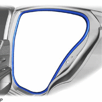
2. REMOVE REAR DOOR OPENING TRIM WEATHERSTRIP
| (a) Remove the rear door opening trim weatherstrip. |
|
READ NEXT:
 Installation
INSTALLATION CAUTION / NOTICE / HINT HINT:
Use the same procedure for the RH side and LH side.
The following procedure is for the LH side.
PROCEDURE 1. INSTALL REAR DOOR OPENING TRIM WEATHERST
Components
COMPONENTS ILLUSTRATION *1 LUGGAGE COMPARTMENT FLOOR MAT *2 SPARE WHEEL COVER TRAY ILLUSTRATION *1 REAR FLOOR FINISH PLATE *2 LUGGAGE HOLD BELT STRIKER ASSEMBLY ILLUSTRATION
SEE MORE:
Components
COMPONENTS ILLUSTRATION *1 FRONT WHEEL OPENING EXTENSION PAD RH *2 FRONT WHEEL OPENING EXTENSION PAD LH *3 NO. 1 ENGINE UNDER COVER *4 NO. 2 ENGINE UNDER COVER ASSEMBLY *5 FRONT FENDER APRON SEAL LH - - N*m (kgf*cm, ft.*lbf): Specified torque - - ILLUSTRAT
DC/DC Converter Temperature Sensor "A" Circuit Short to Ground (P0C3811,P0C3815,P0C3D11,P0C3D15)
DESCRIPTION The motor generator control ECU (MG ECU) located in the inverter with converter assembly detects the temperature of the boost converter using the temperature sensor built into the boost converter. The motor generator control ECU (MG ECU) detects malfunctions in the boost converter temper
