Lexus ES: Removal
REMOVAL
CAUTION / NOTICE / HINT
The necessary procedures (adjustment, calibration, initialization, or registration) that must be performed after parts are removed and installed, or replaced during antenna cord sub-assembly removal/installation are shown below.
Necessary Procedure After Parts Removed/Installed/Replaced (for HV Model)| Replaced Part or Performed Procedure | Necessary Procedures | Effect/Inoperative Function When Necessary Procedures are not Performed | Link |
|---|---|---|---|
|
*: When performing learning using the Techstream.
Click here | |||
| Disconnect cable from negative auxiliary battery terminal | Perform steering sensor zero point calibration | Lane Control System | |
| Pre-collision System | |||
| Parking Support Brake System* | |||
| Lighting System | |||
| Memorize steering angle neutral point | Parking Assist Monitor System | | |
| Panoramic View Monitor System | | ||
| Initialize power trunk lid system | Power Trunk Lid System | | |
| Removal/installation of the front passenger seat | Zero point calibration (Occupant Classification System) |
| |
CAUTION:
Some of these service operations affect the SRS airbag system. Read the precautionary notices concerning the SRS airbag system before servicing.
.png)
Click here .gif)
NOTICE:
- After the power switch is turned off, the radio receiver assembly records various types of memory and settings. As a result, after turning the power switch off, make sure to wait at least 85 seconds before disconnecting the cable from the negative (-) auxiliary battery terminal. (for Audio and Visual System)
- After the power switch is turned off, the radio receiver assembly records various types of memory and settings. As a result, after turning the power switch off, make sure to wait at least 85 seconds before disconnecting the cable from the negative (-) auxiliary battery terminal. (for Navigation System)
| Replaced Part or Performed Procedure | Necessary Procedures | Effect/Inoperative Function When Necessary Procedures are not Performed | Link |
|---|---|---|---|
|
*: When performing learning using the Techstream.
Click here | |||
| Disconnect cable from negative battery terminal | Perform steering sensor zero point calibration | Lane Control System | |
| Pre-collision System | |||
| Parking Support Brake System* | |||
| Lighting System | |||
| Memorize steering angle neutral point | Parking Assist Monitor System | | |
| Panoramic View Monitor System | | ||
| Initialize power trunk lid system | Power Trunk Lid System | | |
| Removal/installation of the front passenger seat | Zero point calibration (Occupant Classification System) |
| |
CAUTION:
Some of these service operations affect the SRS airbag system. Read the precautionary notices concerning the SRS airbag system before servicing.
Click here
NOTICE:
- After the engine switch is turned off, the radio receiver assembly records various types of memory and settings. As a result, after turning the engine switch off, make sure to wait at least 85 seconds before disconnecting the cable from the negative (-) battery terminal. (for Audio and Visual System)
- After the engine switch is turned off, the radio receiver assembly records various types of memory and settings. As a result, after turning the engine switch off, make sure to wait at least 85 seconds before disconnecting the cable from the negative (-) battery terminal. (for Navigation System)
PROCEDURE
1. REMOVE INSTRUMENT PANEL SAFETY PAD SUB-ASSEMBLY
Click here
2. REMOVE NO. 2 SIDE DEFROSTER NOZZLE DUCT
Click here
3. REMOVE NO. 3 HEATER TO REGISTER DUCT
Click here
4. REMOVE ANTENNA CORD SUB-ASSEMBLY
(a) Disconnect the connector.
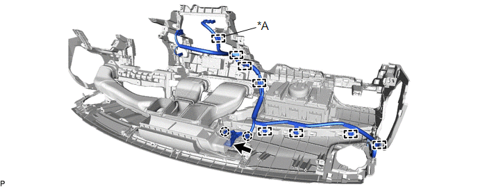
| *A | w/ Manual (SOS) Switch | - | - |
(b) Disengage the 2 claws.
(c) w/o Manual (SOS) Switch:
(1) Disengage the 7 clamps and remove the antenna cord sub-assembly.
(d) w/ Manual (SOS) Switch:
(1) Disengage the 8 clamps and remove the antenna cord sub-assembly.
5. REMOVE ROOF HEADLINING ASSEMBLY
Click here
6. REMOVE NO. 2 ANTENNA CORD SUB-ASSEMBLY
(a) Disengage the clamp and 3 guides.
for Moon Roof:
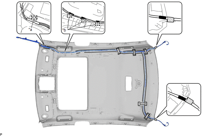
| *a | Clamp | *b | Guide |
.png) | Adhesive Tape | - | - |
for Panoramic Moon Roof:
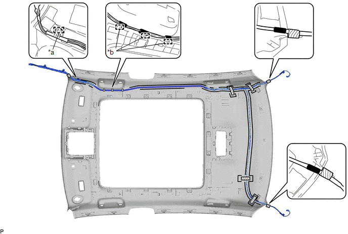
| *a | Clamp | *b | Guide |
| | Adhesive Tape | - | - |
(b) Remove the adhesive tape from the roof headlining assembly.
(c) Remove the No. 2 antenna cord sub-assembly from the roof headlining assembly.
7. REMOVE NO. 3 ANTENNA CORD SUB-ASSEMBLY (w/ Manual (SOS) Switch)
| (a) Disconnect the connector. |
|
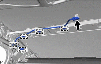
(b) Disengage the 5 clamps to remove the No. 3 antenna cord sub-assembly.
READ NEXT:
 Components
COMPONENTS ILLUSTRATION *1 CENTER INSTRUMENT CLUSTER FINISH PANEL SUB-ASSEMBLY *2 INSTRUMENT PANEL FINISH PANEL END LH *3 INSTRUMENT PANEL FINISH PANEL END RH *4 REAR UPPER CONSOLE
Installation
INSTALLATION PROCEDURE 1. INSTALL NO. 2 RADIO BRACKET HINT: Perform this procedure only when replacement of the No. 2 radio bracket is necessary. (a) Install the No. 2 radio bracket with the 3 screws.
SEE MORE:
Data List / Active Test
DATA LIST / ACTIVE TEST DATA LIST NOTICE: In the table below, the values listed under "Normal Condition" are reference values. Do not depend solely on these reference values when deciding whether a part is faulty or not. HINT: Using the Techstream to read the Data List allows the values or states of
Lost Communication With ECM/PCM "A" Missing Message (U010087,U029387,U117087)
DESCRIPTION The motor generator control ECU communicates with the hybrid vehicle control ECU, ECM and skid control ECU assembly via CAN communication. DTC No. Detection Item DTC Detection Condition Trouble Area MIL Warning Indicate U010087 Lost Communication With ECM/PCM "A" Missi
