
Lexus ES: Vehicle Speed Sensor (B2415)
DESCRIPTION
The headlight ECU sub-assembly LH receives speed signals from the skid control ECU (brake booster with master cylinder assembly) via CAN communication and performs light control.
for LED Type Turn Signal Light| DTC No. | Detection Item | DTC Detection Condition | Trouble Area | DTC Output from |
|---|---|---|---|---|
| B2415 | Vehicle Speed Sensor |
| Electronically controlled brake system | AFS |
| DTC No. | Detection Item | DTC Detection Condition | Trouble Area | DTC Output from |
|---|---|---|---|---|
| B2415 | Vehicle Speed Sensor |
| Electronically controlled brake system | HL AutoLeveling |
WIRING DIAGRAM
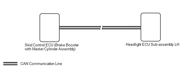
PROCEDURE
| 1. | CONFIRM MODEL |
(a) Choose the model to be inspected.
| Result | Proceed to |
|---|---|
| for LED Type Turn Signal Light | A |
| for Bulb Type Turn Signal Light | B |
| B | .gif) | GO TO STEP 4 |
|
.gif)
| 2. | CLEAR DTC |
(a) Connect the Techstream to the DLC3.
(b) Turn the power switch on (IG).
(c) Turn the Techstream on.
(d) Enter the following menus: Body Electrical / AFS / Trouble Codes.
(e) Clear the DTCs.
Body Electrical > AFS > Clear DTCs
|
| 3. | CHECK FOR DTC |
(a) Connect the Techstream to the DLC3.
(b) Turn the power switch on (IG).
(c) Wait 10 seconds or more.
(d) Turn the Techstream on.
(e) Enter the following menus: Body Electrical / AFS / Trouble Codes.
(f) Check for DTCs.
Body Electrical > AFS > Trouble CodesOK:
DTC B2415 is not output.
| OK | | USE SIMULATION METHOD TO CHECK |
| NG | | GO TO ELECTRONICALLY CONTROLLED BRAKE SYSTEM |
| 4. | CLEAR DTC |
(a) Connect the Techstream to the DLC3.
(b) Turn the power switch on (IG).
(c) Turn the Techstream on.
(d) Enter the following menus: Body Electrical / HL AutoLeveling / Trouble Codes.
(e) Clear the DTCs.
Body Electrical > HL AutoLeveling > Clear DTCs
|
| 5. | CHECK FOR DTC |
(a) Connect the Techstream to the DLC3.
(b) Turn the power switch on (IG).
(c) Wait 10 seconds or more.
(d) Turn the Techstream on.
(e) Enter the following menus: Body Electrical / HL AutoLeveling / Trouble Codes.
(f) Check for DTCs.
Body Electrical > HL AutoLeveling > Trouble CodesOK:
DTC B2415 is not output.
| OK | | USE SIMULATION METHOD TO CHECK |
| NG | | GO TO ELECTRONICALLY CONTROLLED BRAKE SYSTEM |
READ NEXT:
 Rear Height Control Sensor (B241A)
DESCRIPTION The headlight ECU sub-assembly LH determines the vehicle height and performs automatic headlight beam level control based on signals from the rear height control sensor sub-assembly LH via
Headlight Beam Level Control Motor LH Lost Communication (B2424,B2425)
DESCRIPTION Each headlight ECU sub-assembly and headlight leveling motor communicate via LIN communication. The headlight leveling motor operates according to power supplied and automatic headlight be
Right Headlight ECU Malfunction (B242C,B242D)
DESCRIPTION The headlight ECU sub-assembly LH or headlight ECU sub-assembly RH stores a DTC if it detects an internal malfunction. for LED Type Turn Signal Light DTC No. Detection Item DTC Dete
SEE MORE:
Check Bus 5 Lines for Short Circuit
DESCRIPTION There may be a short circuit between the CAN main bus lines and/or CAN branch lines when the resistance between terminals 15 (CA5H) and 16 (CA5L) of the central gateway ECU (network gateway ECU) is below 54 Ω. Symptom Trouble Area Resistance between terminals 15 (CA5H) and 16 (
Removal
REMOVAL CAUTION / NOTICE / HINT The necessary procedures (adjustment, calibration, initialization or registration) that must be performed after parts are removed and installed, or replaced during auxiliary battery removal/installation are shown below. Necessary Procedures After Parts Removed/Install
