Lexus ES: Removal
REMOVAL
CAUTION / NOTICE / HINT
The necessary procedures (adjustment, calibration, initialization, or registration) that must be performed after parts are removed and installed, or replaced during luggage door opening cancel switch assembly removal/installation are shown below.
Necessary Procedure After Parts Removed/Installed/Replaced (for Gasoline Model)| Replaced Part or Performed Procedure | Necessary Procedure | Effect/Inoperative Function when Necessary Procedure not Performed | Link |
|---|---|---|---|
|
*: When performing learning using the Techstream.
Click here | |||
| Disconnect cable from negative battery terminal | Perform steering sensor zero point calibration | Lane Control System | |
| Pre-collision System | |||
| Parking Support Brake System* | |||
| Lighting System | |||
| Memorize steering angle neutral point | Parking Assist Monitor System | | |
| Panoramic View Monitor System | | ||
| Initialize power trunk lid system | Power Trunk Lid System | | |
CAUTION:
Some of these service operations affect the SRS airbag system. Read the precautionary notices concerning the SRS airbag system before servicing.
.png)
Click here .gif)
NOTICE:
- After the engine switch is turned off, the radio receiver assembly records various types of memory and settings. As a result, after turning the engine switch off, make sure to wait at least 85 seconds before disconnecting the cable from the negative (-) battery terminal. (for Audio and Visual System)
- After the engine switch is turned off, the radio receiver assembly records various types of memory and settings. As a result, after turning the engine switch off, make sure to wait at least 85 seconds before disconnecting the cable from the negative (-) battery terminal. (for Navigation System)
| Replaced Part or Performed Procedure | Necessary Procedure | Effect/Inoperative Function When Necessary Procedures are not Performed | Link |
|---|---|---|---|
|
*: When performing learning using the Techstream.
Click here | |||
| Disconnect cable from negative auxiliary battery terminal | Perform steering sensor zero point calibration | Lane Control System | |
| Pre-collision System | |||
| Parking Support Brake System* | |||
| Lighting System | |||
| Memorize steering angle neutral point | Parking Assist Monitor System | | |
| Panoramic View Monitor System | | ||
| Initialize power trunk lid system | Power Trunk Lid System | | |
CAUTION:
Some of these service operations affect the SRS airbag system. Read the precautionary notices concerning the SRS airbag system before servicing.
Click here
NOTICE:
- After the power switch is turned off, the radio receiver assembly records various types of memory and settings. As a result, after turning the power switch off, make sure to wait at least 85 seconds before disconnecting the cable from the negative (-) auxiliary battery terminal. (for Audio and Visual System)
- After the power switch is turned off, the radio receiver assembly records various types of memory and settings. As a result, after turning the power switch off, make sure to wait at least 85 seconds before disconnecting the cable from the negative (-) auxiliary battery terminal. (for Navigation System)
PROCEDURE
1. REMOVE LOWER NO. 2 INSTRUMENT PANEL AIRBAG ASSEMBLY
Click here
2. REMOVE GLOVE COMPARTMENT DOOR ASSEMBLY
Click here
3. REMOVE LUGGAGE DOOR OPENING CANCEL SWITCH ASSEMBLY
(a) Disengage the 2 claws to remove the luggage door opening cancel switch assembly as shown in the illustration.
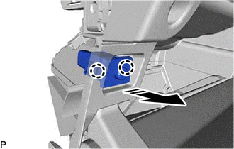
.png) | Remove in this Direction |
READ NEXT:
 Inspection
INSPECTION PROCEDURE 1. INSPECT LUGGAGE DOOR OPENING CANCEL SWITCH ASSEMBLY (a) Check the resistance. (1) Measure the resistance according to the value(s) in the table below. Standard Resistance:
Installation
INSTALLATION PROCEDURE 1. INSTALL LUGGAGE DOOR OPENING CANCEL SWITCH ASSEMBLY (a) Engage the 2 claws to install the luggage door opening cancel switch assembly as shown in the illustration. Ins
Luggage Compartment Door Opener Outer Switch
ComponentsCOMPONENTS ILLUSTRATION *1 LUGGAGE ELECTRICAL KEY SWITCH - - RemovalREMOVAL PROCEDURE 1. REMOVE LUGGAGE COMPARTMENT DOOR OUTSIDE GARNISH SUB-ASSEMBLY Click here 2. REMOVE LU
SEE MORE:
Manifold Absolute Pressure / Barometric Pressure Sensor Signal Stuck in Range (P01052A)
DESCRIPTION Refer to DTC P010511. Click here DTC No. Detection Item DTC Detection Condition Trouble Area MIL Memory Note P01052A Manifold Absolute Pressure / Barometric Pressure Sensor Signal Stuck in Range Intake manifold pressure measured after engine start drops by less t
Replacement
REPLACEMENT PROCEDURE 1. REPLACE INTAKE VALVE GUIDE BUSH (a) Heat the cylinder head sub-assembly to between 80 and 100°C (176 and 212°F). (b) Place the cylinder head sub-assembly on wooden blocks. CAUTION: Be sure to wear protective gloves. (c) Using SST and a hammer, tap out the intake valve g
