Lexus ES: Luggage Compartment Door Opener Outer Switch
Components
COMPONENTS
ILLUSTRATION
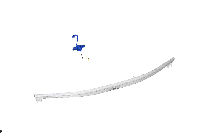
| *1 | LUGGAGE ELECTRICAL KEY SWITCH | - | - |
Removal
REMOVAL
PROCEDURE
1. REMOVE LUGGAGE COMPARTMENT DOOR OUTSIDE GARNISH SUB-ASSEMBLY
Click here .gif)
2. REMOVE LUGGAGE ELECTRICAL KEY SWITCH
| (a) Disconnect the connector. |
|
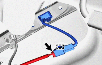
(b) Disengage the clamp.
(c) Disengage the claw and remove the luggage electrical key switch.
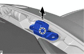
.png) | Remove in this Direction |
Inspection
INSPECTION
PROCEDURE
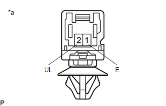
1. INSPECT LUGGAGE ELECTRICAL KEY SWITCH
(a) Check the switch.
| (1) Measure the resistance according to the value(s) in the table below. Standard Resistance:
If the result is not as specified, replace the luggage electrical key switch. |
|
Installation
INSTALLATION
PROCEDURE
1. INSTALL LUGGAGE ELECTRICAL KEY SWITCH
(a) Engage the claw to install the luggage electrical key switch.

.png) | Install in this Direction |
(b) Engage the clamp.
(c) Connect the connector.
2. INSTALL LUGGAGE COMPARTMENT DOOR OUTSIDE GARNISH SUB-ASSEMBLY
Click here .gif)
READ NEXT:
 Precaution
PRECAUTION PRECAUTION FOR DISCONNECTING CABLE FROM NEGATIVE BATTERY TERMINAL NOTICE: When disconnecting the cable from the negative (-) battery terminal, initialize the following systems after the cab
Parts Location
PARTS LOCATION ILLUSTRATION *1 TRUNK AND FUEL SWITCH ASSEMBLY *2 LUGGAGE DOOR OPENING CANCEL SWITCH ASSEMBLY *3 DLC3 *4 MAIN BODY ECU (MULTIPLEX NETWORK BODY ECU) *5 INSTRUME
SEE MORE:
DC/DC Converter Voltage Sensor "A"(VL) Stuck On (P1CB59E)
DTC SUMMARY MALFUNCTION DESCRIPTION If an overvoltage malfunction occurs in the boost converter, the motor generator control ECU (MG ECU) detects the malfunction and stores this DTC. The cause of this malfunction may be one of the following: Internal inverter malfunction
Inverter with converter a
IG1 Voltage Supply too High (C1417,C14DF)
DESCRIPTION If a malfunction is detected in the power source circuit, the skid control ECU (brake booster with master cylinder assembly) stores DTC C1417 and prohibits operation of ABS, brake assist, regenerative brake cooperative control, etc. DTC C1417 is stored if an excessive ECU voltage due to
