Lexus ES: Removal
REMOVAL
PROCEDURE
1. REMOVE FRONT WHEEL LH
Click here .gif)
2. REMOVE FRONT WHEEL OPENING EXTENSION PAD LH
HINT:
Use the same procedure as for the RH side.
Click here
3. REMOVE REAR FENDER SPLASH SHIELD SUB-ASSEMBLY LH
HINT:
Use the same procedure as for the RH side.
Click here
4. REMOVE PIN HOLD CLIP
HINT:
Use the same procedure as for the RH side.
Click here
5. REMOVE FRONT FENDER LINER RETAINER
Click here
6. REMOVE COOL AIR INTAKE DUCT SEAL
Click here
7. REMOVE VEHICLE APPROACHING SPEAKER ASSEMBLY (for HV Model)
Click here
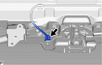
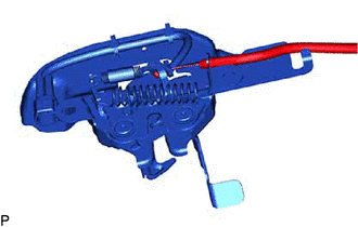
8. REMOVE HOOD LOCK ASSEMBLY
(a) except TMMK Made Gasoline Model:
| (1) Disconnect the connector. |
|
(b) for TMMK Made Gasoline Model:
| (1) Disengage the clamp. |
|
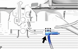
(2) Disconnect the connector.
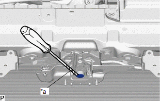
| (c) Using a screwdriver with its tip wrapped with protective tape, remove the hood lock nut cap. |
|
| (d) Remove the 2 bolts and hood lock bolt. |
|
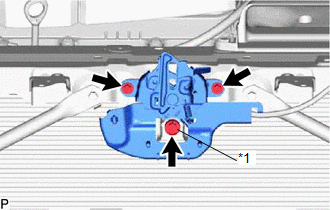
| (e) Disconnect the hood lock control cable assembly to remove the hood lock assembly. |
|
9. REMOVE FRONT DOOR SCUFF PLATE LH
Click here
10. REMOVE COWL SIDE TRIM BOARD LH
Click here
11. REMOVE FRONT DOOR OPENING TRIM COVER LH
Click here
12. REMOVE INSTRUMENT SIDE PANEL LH
Click here
13. REMOVE NO. 1 INSTRUMENT PANEL UNDER COVER SUB-ASSEMBLY
Click here
14. REMOVE LOWER INSTRUMENT PANEL FINISH PANEL SUB-ASSEMBLY
Click here
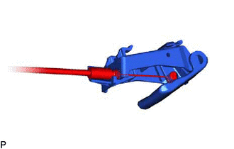
15. REMOVE HOOD LOCK CONTROL LEVER SUB-ASSEMBLY
| (a) Disconnect the hood lock control cable assembly to remove the hood lock control lever sub-assembly. |
|
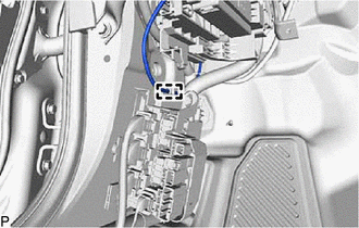
16. REMOVE HOOD LOCK CONTROL CABLE ASSEMBLY
| (a) Disengage the clamp. |
|
(b) Using a screwdriver, disengage each clamp and the grommet as shown in the illustration.
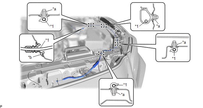
| *1 | Hood Lock Control Cable Assembly | - | - |
| *a | Clamp | *b | Grommet |
HINT:
Tape the screwdriver tip before use.
(c) Pull the hood lock control cable assembly from the engine compartment to remove it.
READ NEXT:
 Removal
REMOVAL PROCEDURE 1. REMOVE FRONT WHEEL LH Click here 2. REMOVE FRONT WHEEL OPENING EXTENSION PAD LH HINT: Use the same procedure as for the RH side. Click here 3. REMOVE REAR FENDER SPLASH SHIELD
Installation
INSTALLATION PROCEDURE 1. INSTALL HOOD LOCK CONTROL CABLE ASSEMBLY (a) Pass the hood lock control cable assembly into the engine compartment. (b) Engage the grommet. (c) Engage each clamp. (d) Engage
Installation
INSTALLATION PROCEDURE 1. INSTALL HOOD LOCK CONTROL CABLE ASSEMBLY (a) Pass the hood lock control cable assembly into the engine compartment. (b) Engage the grommet. (c) Engage each clamp. (d) Engage
SEE MORE:
Warning lights and indicators
The warning lights and indicators on the instrument cluster, center
panel and
outside rear view mirrors inform the driver of the status of the vehicle's
various
systems.
Warning lights and indicators displayed on the instrument cluster
The image may differ from the actual condition.
Warni
Precaution
PRECAUTION PRECAUTION FOR DISCONNECTING CABLE FROM NEGATIVE BATTERY TERMINAL NOTICE: When disconnecting the cable from the negative (-) battery terminal, initialize the following system(s) after the cable is reconnected. System See Procedure Lane Control System (for Gasoline Model)
