Lexus ES: VC Output Circuit
DESCRIPTION
The ECM constantly generates a 5 V power source voltage from the auxiliary battery voltage supplied to the +B, +B2 (BATT) terminals to operate the microprocessor. The ECM also provides this power to the sensors through the VC output circuit.
.png)
When the VC circuit has a short circuit, the microprocessor in the ECM and sensors that are supplied power through the VC circuit are deactivated because power is not supplied from the VC circuit. When the system is in this condition, it will not start.
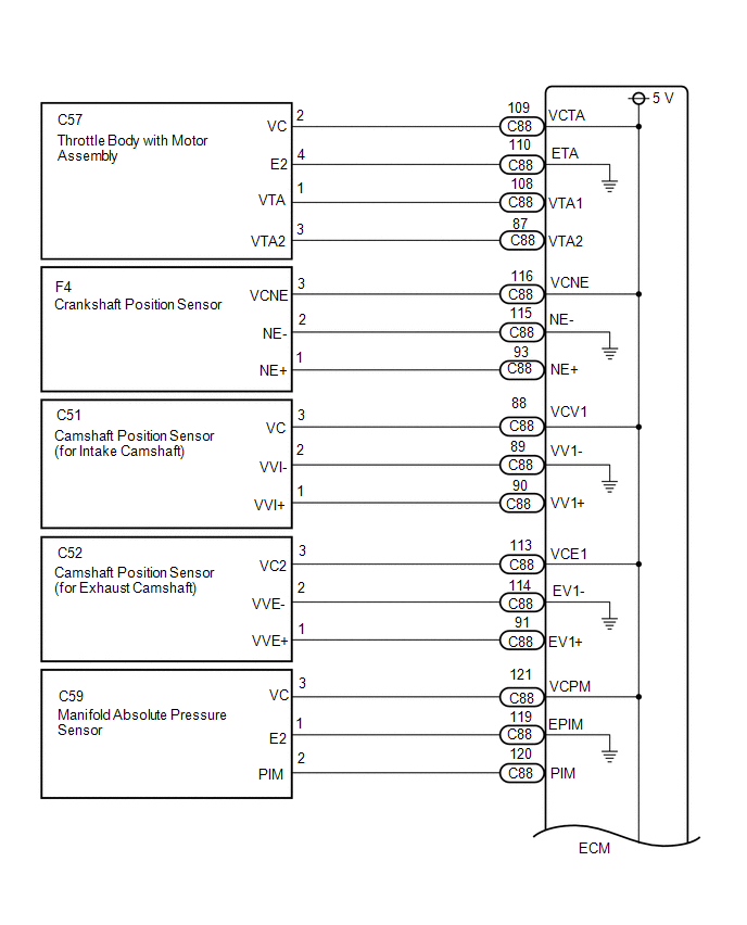
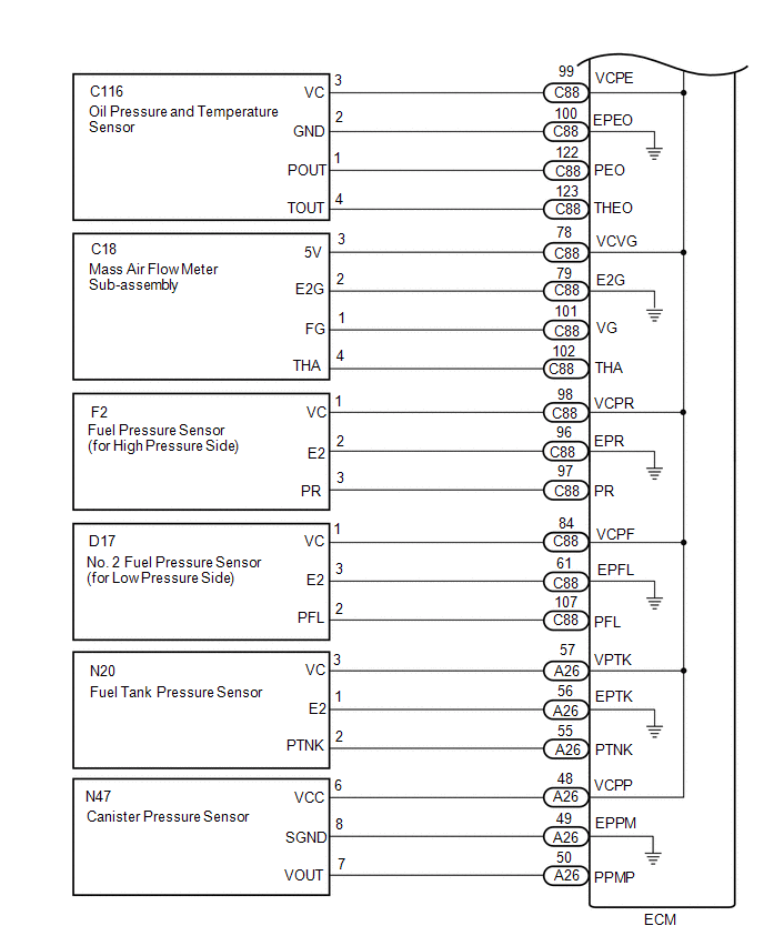
WIRING DIAGRAM
-
For the circuit diagram of the ECM power source refer to the ECM power source circuit.
Click here
.gif)
-
VC Output Circuit
CAUTION / NOTICE / HINT
NOTICE:
Check the fuses for circuits related to this system before performing the following inspection procedure.
PROCEDURE
| 1. | CHECK CONNECTION BETWEEN TECHSTREAM AND ECM |
(a) Connect the Techstream to the DLC3.
(b) Turn the power switch on (IG).
(c) Turn the Techstream on.
(d) Check the communication between the Techstream and ECM.
HINT:
It can be checked using the "Engine" item of the Data List.
| Result | Proceed to |
|---|---|
| Communication is not possible | A |
| Communication is possible | B |
| B | .gif) | PROCEED TO NEXT SUSPECTED AREA SHOWN IN PROBLEM SYMPTOMS TABLE |
|
.gif)
| 2. | CHECK EFI NO. 1 FUSE VOLTAGE |
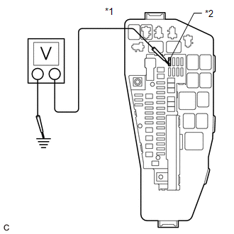
| *1 | No. 1 Engine Room Relay Block and No. 1 Junction Block Assembly |
| *2 | EFI NO. 1 Fuse |
(a) Turn the power switch on (IG).
(b) Measure the voltage according to the value(s) in the table below.
Standard Voltage:
| Tester Connection | Condition | Specified Condition |
|---|---|---|
| 1 (EFI NO. 1 fuse) - Body ground | Power switch on (IG) | 11 to 14 V |
HINT:
- Check the fuse with it installed to the No. 1 engine room relay block and No. 1 junction block assembly.
- If the result is not as specified, since current is not flowing to the +B and +B2 terminals of the ECM, the system may not be started.
| NG | | GO TO ECM POWER SOURCE CIRCUIT |
|
| 3. | CHECK CONNECTION BETWEEN TECHSTREAM AND ECM (THROTTLE POSITION SENSOR) |
(a) Disconnect the throttle body with motor assembly connector.
(b) Turn the power switch on (IG).
(c) Turn the Techstream on.
(d) Check the communication between the Techstream and ECM.
HINT:
It can be checked using the "Engine" item of the Data List.
| Result | Proceed to |
|---|---|
| Communication is not possible | A |
| Communication is possible | B |
HINT:
Perform "Inspection After Repair" after replacing the throttle body with motor assembly.
Click here
| B | | REPLACE THROTTLE BODY WITH MOTOR ASSEMBLY |
|
| 4. | CHECK CONNECTION BETWEEN TECHSTREAM AND ECM (CRANKSHAFT POSITION SENSOR) |
(a) Disconnect the crankshaft position sensor connector.
(b) Turn the power switch on (IG).
(c) Turn the Techstream on.
(d) Check the communication between the Techstream and ECM.
HINT:
It can be checked using the "Engine" item of the Data List.
| Result | Proceed to |
|---|---|
| Communication is not possible | A |
| Communication is possible | B |
| B | | REPLACE CRANKSHAFT POSITION SENSOR |
|
| 5. | CHECK CONNECTION BETWEEN TECHSTREAM AND ECM (CAMSHAFT POSITION SENSOR (FOR INTAKE CAMSHAFT)) |
(a) Disconnect the camshaft position sensor (for intake camshaft) connector.
(b) Turn the power switch on (IG).
(c) Turn the Techstream on.
(d) Check the communication between the Techstream and ECM.
HINT:
It can be checked using the "Engine" item of the Data List.
| Result | Proceed to |
|---|---|
| Communication is not possible | A |
| Communication is possible | B |
| B | | REPLACE CAMSHAFT POSITION SENSOR (FOR INTAKE CAMSHAFT) |
|
| 6. | CHECK CONNECTION BETWEEN TECHSTREAM AND ECM (MANIFOLD ABSOLUTE PRESSURE SENSOR) |
(a) Disconnect the manifold absolute pressure sensor connector.
(b) Turn the power switch on (IG).
(c) Turn the Techstream on.
(d) Check the communication between the Techstream and ECM.
HINT:
It can be checked using the "Engine" item of the Data List.
| Result | Proceed to |
|---|---|
| Communication is not possible | A |
| Communication is possible | B |
| B | | REPLACE MANIFOLD ABSOLUTE PRESSURE SENSOR |
|
| 7. | CHECK CONNECTION BETWEEN TECHSTREAM AND ECM (CAMSHAFT POSITION SENSOR (FOR EXHAUST CAMSHAFT)) |
(a) Disconnect the camshaft position sensor (for exhaust camshaft) connector.
(b) Turn the power switch on (IG).
(c) Turn the Techstream on.
(d) Check the communication between the Techstream and ECM.
HINT:
It can be checked using the "Engine" item of the Data List.
| Result | Proceed to |
|---|---|
| Communication is not possible | A |
| Communication is possible | B |
| B | | REPLACE CAMSHAFT POSITION SENSOR (FOR EXHAUST CAMSHAFT) |
|
| 8. | CHECK CONNECTION BETWEEN TECHSTREAM AND ECM (OIL PRESSURE AND TEMPERATURE SENSOR) |
(a) Disconnect the oil pressure and temperature sensor connector.
(b) Turn the power switch on (IG).
(c) Turn the Techstream on.
(d) Check the communication between the Techstream and ECM.
HINT:
It can be checked using the "Engine" item of the Data List.
| Result | Proceed to |
|---|---|
| Communication is not possible | A |
| Communication is possible | B |
| B | | REPLACE OIL PRESSURE AND TEMPERATURE SENSOR |
|
| 9. | CHECK CONNECTION BETWEEN TECHSTREAM AND ECM (FUEL PRESSURE SENSOR (FOR HIGH PRESSURE SIDE)) |
(a) Disconnect the fuel pressure sensor (for high pressure side) connector.
(b) Turn the power switch on (IG).
(c) Turn the Techstream on.
(d) Check the communication between the Techstream and ECM.
HINT:
It can be checked using the "Engine" item of the Data List.
| Result | Proceed to |
|---|---|
| Communication is not possible | A |
| Communication is possible | B |
HINT:
Perform "Inspection After Repair" after replacing the fuel pressure sensor (for high pressure side).
Click here
| B | | REPLACE FUEL PRESSURE SENSOR (FOR HIGH PRESSURE SIDE) |
|
| 10. | CHECK CONNECTION BETWEEN TECHSTREAM AND ECM (NO. 2 FUEL PRESSURE SENSOR (FOR LOW PRESSURE SIDE)) |
(a) Disconnect the No. 2 fuel pressure sensor (for low pressure side) connector.
(b) Turn the power switch on (IG).
(c) Turn the Techstream on.
(d) Check the communication between the Techstream and ECM.
HINT:
It can be checked using the "Engine" item of the Data List.
| Result | Proceed to |
|---|---|
| Communication is not possible | A |
| Communication is possible | B |
HINT:
Perform "Inspection After Repair" after replacing the No. 2 fuel pressure sensor (for low pressure side).
Click here
| B | | REPLACE NO. 2 FUEL PRESSURE SENSOR (FOR LOW PRESSURE SIDE) |
|
| 11. | CHECK CONNECTION BETWEEN TECHSTREAM AND ECM (MASS AIR FLOW METER SUB-ASSEMBLY) |
(a) Disconnect the mass air flow meter sub-assembly connector.
(b) Turn the power switch on (IG).
(c) Turn the Techstream on.
(d) Check the communication between the Techstream and ECM.
HINT:
It can be checked using the "Engine" item of the Data List.
| Result | Proceed to |
|---|---|
| Communication is not possible | A |
| Communication is possible | B |
HINT:
Perform "Inspection After Repair" after replacing the mass air flow meter sub-assembly.
Click here
| B | | REPLACE MASS AIR FLOW METER SUB-ASSEMBLY |
|
| 12. | CHECK CONNECTION BETWEEN TECHSTREAM AND ECM (CANISTER PUMP MODULE) |
(a) Disconnect the canister pump module connector.
(b) Turn the power switch on (IG).
(c) Turn the Techstream on.
(d) Check the communication between the Techstream and ECM.
HINT:
It can be checked using the "Engine" item of the Data List.
| Result | Proceed to |
|---|---|
| Communication is not possible | A |
| Communication is possible | B |
| B | | REPLACE LEAK DETECTION PUMP SUB-ASSEMBLY |
|
| 13. | CHECK CONNECTION BETWEEN TECHSTREAM AND ECM (FUEL TANK PRESSURE SENSOR) |
(a) Disconnect the fuel tank pressure sensor connector.
(b) Turn the power switch on (IG).
(c) Turn the Techstream on.
(d) Check the communication between the Techstream and ECM.
HINT:
It can be checked using the "Engine" item of the Data List.
| Result | Proceed to |
|---|---|
| Communication is not possible | A |
| Communication is possible | B |
| B | | REPLACE FUEL TANK PRESSURE SENSOR |
|
| 14. | CHECK HARNESS AND CONNECTOR |
(a) Disconnect the throttle body with motor assembly connector.
(b) Disconnect the crankshaft position sensor connector.
(c) Disconnect the camshaft position sensor (for intake camshaft) connector.
(d) Disconnect the manifold absolute pressure sensor connector.
(e) Disconnect the camshaft position sensor (for exhaust camshaft) connector.
(f) Disconnect the oil pressure and temperature sensor connector.
(g) Disconnect the fuel pressure sensor (for high pressure side) connector.
(h) Disconnect the No. 2 fuel pressure sensor (for low pressure side) connector.
(i) Disconnect the mass air flow meter sub-assembly connector.
(j) Disconnect the canister pump module connector.
(k) Disconnect the fuel tank pressure sensor connector.
(l) Disconnect the ECM connectors.
(m) Measure the resistance according to the value(s) in the table below.
Standard Resistance:
| Tester Connection | Condition | Specified Condition |
|---|---|---|
| C88-109 (VCTA) - Body ground | Always | 10 kΩ or higher |
| C88-116 (VCNE) - Body ground | Always | 10 kΩ or higher |
| C88-88 (VCV1) - Body ground | Always | 10 kΩ or higher |
| C88-113 (VCE1) - Body ground | Always | 10 kΩ or higher |
| C88-121 (VCPM) - Body ground | Always | 10 kΩ or higher |
| C88-99 (VCPE) - Body ground | Always | 10 kΩ or higher |
| C88-78 (VCVG) - Body ground | Always | 10 kΩ or higher |
| C88-98 (VCPR) - Body ground | Always | 10 kΩ or higher |
| C88-84 (VCPF) - Body ground | Always | 10 kΩ or higher |
| A26-48 (VCPP) - Body ground | Always | 10 kΩ or higher |
| A26-57 (VPTK) - Body ground | Always | 10 kΩ or higher |
(n) Remove the VVT, EFI-MAIN NO. 2 and A/F HTR relays from the No. 1 engine room relay block and No. 1 junction block assembly.
HINT:
Remove the VVT, EFI-MAIN NO. 2 and A/F HTR relays connected between the checked terminals as the coil inside the relay influences the measurement value.
(o) Measure the resistance according to the value(s) in the table below.
Standard Resistance:
| Tester Connection | Condition | Specified Condition |
|---|---|---|
| A26-9 (+B) - 1 (EFI NO. 1 fuse) | Always | Below 1 Ω |
| A26-35 (+B2) - 1 (EFI NO. 1 fuse) | Always | Below 1 Ω |
| A26-9 (+B) - Body ground | Always | 10 kΩ or higher |
| A26-35 (+B2) - Body ground | Always | 10 kΩ or higher |
| OK | | REPLACE ECM |
| NG | | REPAIR OR REPLACE HARNESS OR CONNECTOR |
READ NEXT:
 MIL Circuit
DESCRIPTION The Malfunction Indicator Lamp (MIL) is used to indicate vehicle malfunctions detected by the ECM. The MIL operation can be checked visually. When the power switch is first turned to on (I
Ignition Circuit
DESCRIPTION A direct ignition system is used on this vehicle. The direct ignition system is a 1 cylinder ignition system which ignites one cylinder with one ignition coil. In the 1 cylinder ignition s
Rough Idling
DESCRIPTION Problem Symptom Suspected Area Trouble Area
Engine speed fluctuation due to abnormal combustion
Idle speed too low or high
Strong engine vibration due to above symptoms
SEE MORE:
Components
COMPONENTS ILLUSTRATION *1 FRONT WHEEL OPENING EXTENSION PAD RH *2 FRONT WHEEL OPENING EXTENSION PAD LH *3 NO. 1 ENGINE UNDER COVER *4 NO. 2 ENGINE UNDER COVER ASSEMBLY *5 FRONT FENDER APRON SEAL LH - - N*m (kgf*cm, ft.*lbf): Specified torque - - ILLUSTRAT
Blind Spot Monitor Master Module Beam Axis Inspection Incomplete (C1ABB)
DESCRIPTION This DTC is stored when a beam axis inspection has not been performed for the blind spot monitor sensor RH. HINT: This DTC is always stored after replacing a blind spot monitor sensor. The purpose of this DTC is to ensure that a beam axis inspection is performed. Completing the beam axis
