
Lexus ES: Removal
REMOVAL
PROCEDURE
1. REMOVE FRONT DOOR SCUFF PLATE LH
Click here .gif)
2. REMOVE COWL SIDE TRIM BOARD LH
Click here
3. REMOVE FRONT DOOR OPENING TRIM COVER LH
Click here
4. REMOVE INSTRUMENT SIDE PANEL LH
Click here
5. REMOVE NO. 1 INSTRUMENT PANEL UNDER COVER SUB-ASSEMBLY
Click here
6. REMOVE LOWER INSTRUMENT PANEL FINISH PANEL SUB-ASSEMBLY
Click here
7. REMOVE FUEL LID OPENER SWITCH (TRUNK AND FUEL SWITCH ASSEMBLY)
(a) Disengage the 2 claws to remove the fuel lid opener switch (trunk and fuel switch assembly) as shown in the illustration.
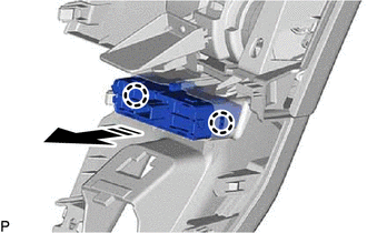
.png) | Remove in this Direction |
READ NEXT:
 Inspection
INSPECTION PROCEDURE 1. INSPECT FUEL LID OPENER SWITCH (TRUNK AND FUEL SWITCH ASSEMBLY) (a) Check the switch. (1) Measure the resistance according to the value(s) in the table below. Standard Resis
Installation
INSTALLATION PROCEDURE 1. INSTALL FUEL LID OPENER SWITCH (TRUNK AND FUEL SWITCH ASSEMBLY) (a) Engage the 2 claws to install the fuel lid opener switch (trunk and fuel switch assembly) as shown in the
SEE MORE:
Brake Hydraulic Pressure Malfunction (C164F)
DESCRIPTION When a malfunction signal sent from the skid control ECU via CAN communication is detected by the clearance warning ECU assembly, DTC C164F is stored. DTC No. Detection Item DTC Detection Condition Trouble Area C164F Brake Hydraulic Pressure Malfunction Brake master cyli
Inspection
INSPECTION PROCEDURE 1. INSPECT FRONT OIL PUMP ASSEMBLY (a) Install the oil pump drive shaft sub-assembly to the front oil pump assembly. NOTICE:
To avoid damaging the bush of the front oil pump assembly, install the oil pump drive shaft sub-assembly perpendicularly relative to the front oil pump
© 2016-2026 Copyright www.lexguide.net
