
Lexus ES: Inspection
INSPECTION
PROCEDURE
1. INSPECT FUEL LID OPENER SWITCH (TRUNK AND FUEL SWITCH ASSEMBLY)
| (a) Check the switch. (1) Measure the resistance according to the value(s) in the table below. Standard Resistance:
If the result is not as specified, replace the fuel lid opener switch (trunk and fuel switch assembly). |
|
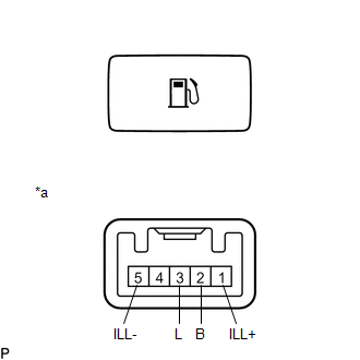
(b) Check the switch illumination.
(1) Apply auxiliary battery voltage to the switch connector and check that the fuel lid opener switch (trunk and fuel switch assembly) illuminates.
OK:
| Auxiliary Battery Condition | Specified Condition |
|---|---|
| Auxiliary battery positive (+) → Terminal 1 (ILL+) Auxiliary battery negative (-) → Terminal 5 (ILL-) | Illumination illuminates |
If the result is not as specified, replace the fuel lid opener switch (trunk and fuel switch assembly).
READ NEXT:
 Installation
INSTALLATION PROCEDURE 1. INSTALL FUEL LID OPENER SWITCH (TRUNK AND FUEL SWITCH ASSEMBLY) (a) Engage the 2 claws to install the fuel lid opener switch (trunk and fuel switch assembly) as shown in the
Precaution
PRECAUTION PRECAUTION FOR DISCONNECTING CABLE FROM NEGATIVE AUXILIARY BATTERY TERMINAL NOTICE: When disconnecting the cable from the negative (-) auxiliary battery terminal, initialize the following s
SEE MORE:
FR Damping Force Control Actuator Circuit (C1731-C1734)
DESCRIPTION The absorber control actuator changes the damping force depending on absorber control ECU signals. DTC No. Detection Item DTC Detection Condition Trouble Area Warning Indicate Memory C1731 FR Damping Force Control Actuator Circuit Either condition is met:
An open
RCD (Rear Camera Detection)
function
When the vehicle is backing up, the
rear camera detection function can
detect pedestrians in the detection
area behind the vehicle. If a pedestrian
is detected, a buzzer will
sound and an icon will be displayed
on the Center Display to inform the
driver of the pedestrian.
Center Display
