Lexus ES: Terminals Of Ecu
TERMINALS OF ECU
CHECK LUGGAGE CLOSER MOTOR ASSEMBLY

(a) Disconnect the R7 luggage closer motor assembly connector.
(b) Measure the voltage and resistance according to the value(s) in the table below.
| Terminal No. (Symbol) | Wiring Color | Terminal Description | Condition | Specified Condition |
|---|---|---|---|---|
| R7-8 (IG) - Body ground | LA-B - Body ground | IG power supply | Engine switch on (IG) | 11 to 14 V |
| Engine switch off | Below 1 V | |||
| R7-10 (ECUB) - Body ground | LA-W - Body ground | Battery power supply | Always | 11 to 14 V |
| R7-12 (B) - Body ground | B - Body ground | Battery power supply | Always | 11 to 14 V |
| R7-11 (GND) - Body ground | W-B - Body ground | Ground | Always | Below 1 Ω |
(c) Reconnect the R7 luggage closer motor assembly connector.
(d) Measure the voltage and check for pulses according to the value(s) in the table below.
| Terminal No. (Symbol) | Wiring Color | Terminal Description | Condition | Specified Condition |
|---|---|---|---|---|
| R7-1 (LCM-) - Body ground | L - Body ground | Luggage compartment door lock motor lock drive output | Power trunk lid close operating | 11 to 14 V |
| Power trunk lid not operating | Below 1 V | |||
| R7-2 (LCM+) - Body ground | LG - Body ground | Luggage compartment door unlock motor lock drive output | Power trunk lid open operating | 11 to 14 V |
| Power trunk lid not operating | Below 1 V | |||
| R7-4 (LDDN) - Body ground | GR - Body ground | Door control switch input | Door control switch on | Below 1 V |
| Door control switch off | 11 to 14 V | |||
| R7-7 (HAF) - Body ground | V - Body ground | Half latch switch input | Luggage compartment door fully open | Below 1 V |
| Luggage compartment door half latched → fully close | 11 to 14 V | |||
| R7-20 (PAWL) - Body ground | P - Body ground | Pawl switch input | Luggage compartment door fully open → fully close | 11 to 14 V → Below 1 V → 11 to 14 V |
| Luggage compartment door fully close → fully open | 11 to 14 V → Below 1 V → 11 to 14 V | |||
| R7-21 (SWG) - Body ground | L - Body ground | Half latch switch and pawl switch ground | Luggage compartment door fully open | Below 1 V |
| Luggage compartment door half latched → fully close | 11 to 14 V | |||
| R7-16 (CSG) - Body ground | W - Body ground | Luggage door closer assembly (pulse sensor) ground | Always | Below 1 Ω |
| R7-17 (CS2) - Body ground | B - Body ground | Luggage door closer assembly (pulse sensor) signal | Luggage door closer assembly operating | Pulse generation (See waveform 1) |
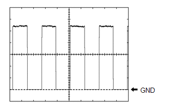
| R7-18 (CS1) - Body ground | G - Body ground | Luggage door closer assembly (pulse sensor) signal | Luggage door closer assembly operating | Pulse generation (See waveform 2) |
| R7-19 (CSV) - Body ground | R - Body ground | Luggage door closer assembly (pulse sensor) power supply | Always | 7 V or higher |
| R7-24 (KSIN) - Body ground | L - Body ground | Kick door control sensor input | Kick door control sensor not detecting a foot → detecting a foot | Pulse generation (See waveform 3) |
(1) Using an oscilloscope, check waveform 1.
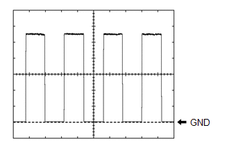 Waveform 1 (Reference)
 | Item | Condition |
|---|---|
| Tester connection | R7-17 (CS2) - Body ground |
| Tool setting | 2 V/DIV, 10 ms/DIV. |
| Vehicle condition | Luggage door closer assembly operating |
HINT:
The period changes in accordance to the speed at which the luggage compartment door is opened and closed.
(2) Using an oscilloscope, check waveform 2.
Waveform 2 (Reference)| Item | Condition |
|---|---|
| Tester connection | R7-18 (CS1) - Body ground |
| Tool setting | 2 V/DIV, 10 ms/DIV. |
| Vehicle condition | Luggage door closer assembly operating |
HINT:
The period changes in accordance to the speed at which the luggage compartment door is opened and closed.
(3) Using an oscilloscope, check waveform 3.
Waveform 3 (Reference)| Item | Condition |
|---|---|
| Tester connection | R7-24 (KSIN) - Body ground |
| Tool setting | 2 V/DIV, 50 ms/DIV. |
| Vehicle condition | Kick door control sensor not detecting a foot → detecting a foot |
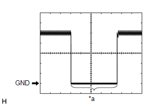
| *a | Kick detection signal |
CHECK INSTRUMENT PANEL JUNCTION BLOCK ASSEMBLY AND MAIN BODY ECU (MULTIPLEX NETWORK BODY ECU)
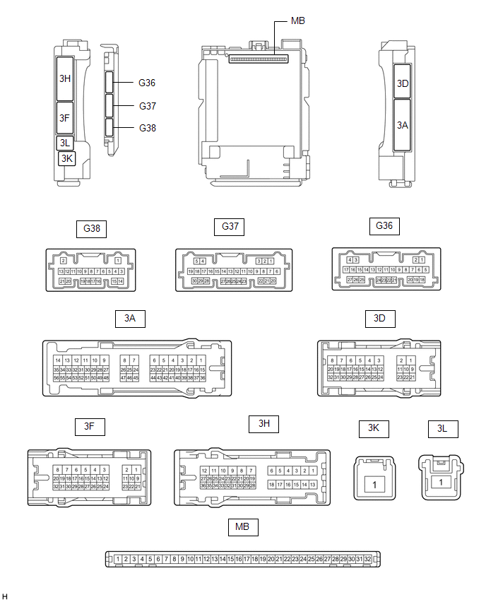
(a) Remove the main body ECU (multiplex network body ECU) from the instrument panel junction block assembly.
Click here .gif)
(b) Measure the resistance according to the value(s) in the table below.
| Terminal No. (Symbol) | Wiring Color | Terminal Description | Condition | Specified Condition |
|---|---|---|---|---|
| G36-19 (GND2) - Body ground | W-B - Body ground | Ground | Always | Below 1 Ω |
(c) Reconnect the instrument panel junction block assembly connectors.
(d) Measure the resistance and voltage according to the value(s) in the table below.
| Terminal No. (Symbol) | Wiring Color | Terminal Description | Condition | Specified Condition |
|---|---|---|---|---|
| MB-11 (GND1) - Body ground | - | Ground | Always | Below 1 Ω |
| MB-30 (ACC) - Body ground | - | ACC power supply | Engine switch on (ACC) | 11 to 14 V |
| Engine switch off | Below 1 V | |||
| MB-31 (BECU) - Body ground | - | Battery power supply | Always | 11 to 14 V |
| MB-32 (IG) - Body ground | - | IG power supply | Engine switch on (IG) | 11 to 14 V |
| Engine switch off | Below 1 V |
(e) Install the main body ECU (multiplex network body ECU) to the instrument panel junction block assembly.
Click here
(f) Measure the voltage and check for pulses according to the value(s) in the table below.
| Terminal No. (Symbol) | Wiring Color | Terminal Description | Condition | Specified Condition |
|---|---|---|---|---|
| G38-4 (TSW) - Body ground | LG - Body ground | Luggage compartment door opening switch input | Trunk and fuel switch assembly (luggage compartment door opening switch) on | Below 1 V |
| Engine switch off, all doors closed and trunk and fuel switch assembly (luggage compartment door opening switch) off | Pulse generation | |||
| G38-27 (TMSW) - Body ground | B - Body ground | Luggage door opening cancel switch assembly input | Luggage door opening cancel switch assembly on | Below 1 V |
| Engine switch off, all doors closed and luggage door opening cancel switch assembly off | 11 to 14 V |
CHECK CERTIFICATION ECU (SMART KEY ECU ASSEMBLY)
Click here
READ NEXT:
 Dtc Check / Clear
DTC CHECK / CLEAR CHECK DTC (a) Connect the Techstream to the DLC3. (b) Turn the engine switch on (IG). (c) Turn the Techstream on. (d) Enter the following menus: Body Electrical / Back Door / Trouble
Data List / Active Test
DATA LIST / ACTIVE TEST DATA LIST NOTICE: In the table below, the values listed under "Normal Condition" are reference values. Do not depend solely on these reference values when deciding whether a pa
Diagnostic Trouble Code Chart
DIAGNOSTIC TROUBLE CODE CHART Power Trunk Lid System DTC No. Detection Item Link B2205 Kick Sensor Circuit B2222 PBD/PTL Pulse Sensor B2225 PBD/PTL Motor Clutch Malf
SEE MORE:
Radio Receiver Power Source Circuit
DESCRIPTION This is the power source circuit to operate the radio receiver assembly. WIRING DIAGRAM CAUTION / NOTICE / HINT NOTICE: Inspect the fuses for circuits related to this system before performing the following procedure. PROCEDURE 1. CHECK HARNESS AND CONNECTOR (RADIO RECEIVER ASSEMBL
Discharging
DISCHARGING PROCEDURE 1. DISCHARGING (WHEN USING THE LI-ION BATTERY DISCHARGER) CAUTION: Be sure to wear insulated gloves and protective goggles. NOTICE: Make sure to observe the following points when using the Li-ion battery discharger.
Set it in a secure, flat place.
Set it in a dry place pro
