Lexus ES: Removal
REMOVAL
CAUTION / NOTICE / HINT
HINT:
for Side:- Use the same procedure for the RH side and LH side.
- The following procedure is for the LH side.
PROCEDURE
1. REMOVE FRONT DOOR SCUFF PLATE (for Side)
Click here .gif)
2. REMOVE COWL SIDE TRIM BOARD (for Side)
Click here
3. REMOVE FRONT DOOR OPENING TRIM COVER (for Side)
Click here
4. REMOVE FRONT PILLAR GARNISH ASSEMBLY (for Side)
Click here
5. REMOVE NO. 1 INSTRUMENT PANEL SPEAKER PANEL SUB-ASSEMBLY (for Side)
Click here
6. REMOVE FRONT NO. 2 SPEAKER ASSEMBLY (for Side)
NOTICE:
Do not touch the speaker cone.
| (a) Remove the 2 bolts. |
|
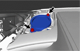
(b) Lift the front No. 2 speaker assembly and disconnect the connector to remove it.
7. REMOVE NO. 1 SPEAKER OPENING COVER ASSEMBLY (for Center)
Click here
8. REMOVE FRONT NO. 3 SPEAKER ASSEMBLY (for Center)
NOTICE:
Do not touch the speaker cone.
| (a) Remove the 2 bolts. |
|
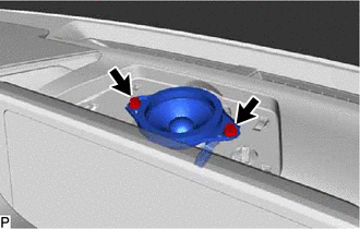
(b) Lift the front No. 3 speaker assembly and disconnect the connector to remove it.
READ NEXT:
 Components
COMPONENTS ILLUSTRATION *1 TELEPHONE MICROPHONE ASSEMBLY - -
Installation
INSTALLATION PROCEDURE 1. INSTALL TELEPHONE MICROPHONE ASSEMBLY (a) Connect the connector. Install in this Direction (b) Engage the 2 claws to install the telephone microphone assembly as sh
SEE MORE:
Basic Inspection
CAUTION / NOTICE / HINT When a malfunction is not confirmed by the DTC check, troubleshooting should be carried out for all circuits considered to be possible causes of the problem. In many cases, by carrying out the basic engine check shown in the following procedure, the location of the problem ca
Lack of Power
DESCRIPTION Problem Symptom Suspected Area Trouble Area
Engine speed fluctuation due to abnormal combustion
Idle speed too low or high
Strong engine vibration due to above symptoms
Ignition malfunction
Deviation in air fuel ratio (Excessive or insufficient intake air volume
