Lexus ES: Components
COMPONENTS
ILLUSTRATION
.png)
| *1 | BATTERY SERVICE HOLE COVER | *2 | SERVICE PLUG GRIP |
ILLUSTRATION
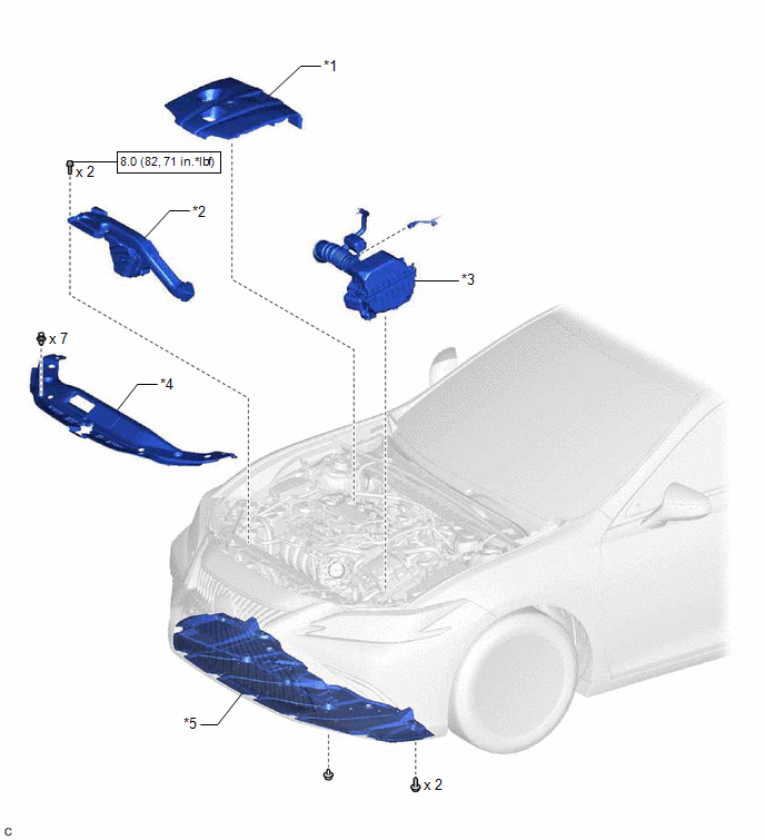
| *1 | NO. 1 ENGINE COVER SUB-ASSEMBLY | *2 | INLET AIR CLEANER ASSEMBLY |
| *3 | AIR CLEANER ASSEMBLY WITH AIR CLEANER HOSE | *4 | COOL AIR INTAKE DUCT SEAL |
| *5 | NO. 1 ENGINE UNDER COVER | - | - |
.png) | N*m (kgf*cm, ft.*lbf): Specified torque | - | - |
ILLUSTRATION
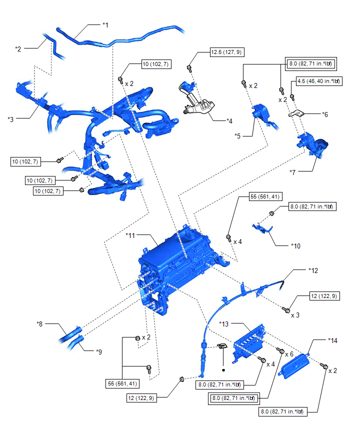
| *1 | NO. 1 FUEL VAPOR FEED HOSE | *2 | NO. 2 FUEL VAPOR FEED HOSE |
| *3 | ENGINE WIRE | *4 | ENGINE ROOM MAIN WIRE |
| *5 | HV AIR CONDITIONING WIRE | *6 | CONNECTOR COVER ASSEMBLY |
| *7 | HV FLOOR UNDER WIRE | *8 | NO. 1 INVERTER COOLING HOSE |
| *9 | NO. 4 INVERTER COOLING HOSE | *10 | WIRE HARNESS CLAMP BRACKET |
| *11 | INVERTER WITH CONVERTER ASSEMBLY | *12 | TRANSMISSION CONTROL CABLE ASSEMBLY |
| *13 | MOTOR CABLE | *14 | INVERTER COVER |
.png) | Tightening torque for "Major areas involving basic vehicle performance such as moving/turning/stopping": N*m (kgf*cm, ft.*lbf) | | N*m (kgf*cm, ft.*lbf): Specified torque |
| ● | Non-reusable part | - | - |
ILLUSTRATION
.png)
| *1 | WIRE HARNESS CLAMP BRACKET | *2 | INVERTER WITH CONVERTER ASSEMBLY |
| *3 | NO. 1 INVERTER BRACKET | *4 | NO. 2 INVERTER BRACKET |
| *5 | INVERTER PROTECTOR | - | - |
| | N*m (kgf*cm, ft.*lbf): Specified torque | - | - |
READ NEXT:
 Removal
REMOVAL CAUTION / NOTICE / HINT The necessary procedures (adjustment, calibration, initialization or registration) that must be performed after parts are removed and installed, or replaced during inve
Installation
INSTALLATION PROCEDURE 1. INSTALL INVERTER PROTECTOR (a) Install the inverter protector to the inverter with converter assembly with the bolt. Torque: 9.5 N·m {97 kgf·cm, 84 in·lbf} NOTICE: Mak
SEE MORE:
System Voltage (BATT) Circuit Short to Ground or Open (P056014)
DESCRIPTION Auxiliary battery power is supplied to the BATT terminal of the hybrid vehicle control ECU in order to store DTCs and freeze frame data. Even if the power switch is turned off, back-up power is supplied. DTC No. Detection Item DTC Detection Condition Trouble Area MIL Warning
Communication Error from ECM to VSC Invalid Serial Data Received (P163181)
DESCRIPTION The skid control ECU (brake booster with master cylinder assembly) sends signals such as brake request signals to the hybrid vehicle control ECU. When the hybrid vehicle control ECU detects logic error signals sent from the skid control ECU (brake booster with master cylinder assembly) f
