Lexus ES: Removal
REMOVAL
CAUTION / NOTICE / HINT
HINT:
- Use the same procedure for the RH side and LH side.
- The following procedure is for the LH side.
PROCEDURE
1. REMOVE NO. 2 DOOR TRIM PAD
Click here .gif)
2. REMOVE MULTIPLEX NETWORK MASTER SWITCH ASSEMBLY WITH FRONT DOOR UPPER ARMREST BASE PANEL (for Driver Side)
Click here
3. REMOVE POWER WINDOW REGULATOR SWITCH ASSEMBLY WITH FRONT DOOR UPPER ARMREST BASE PANEL (for Front Passenger Side)
Click here
4. REMOVE COURTESY LIGHT ASSEMBLY
Click here
5. REMOVE FRONT DOOR TRIM BOARD SUB-ASSEMBLY
Click here
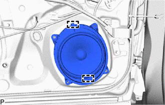
6. REMOVE FRONT NO. 1 SPEAKER ASSEMBLY
NOTICE:
Do not touch the speaker cone.
| (a) Disconnect the connector. |
|
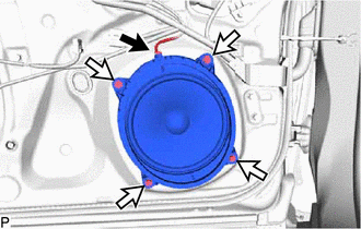
(b) Remove the 4 screws.
| (c) Disengage the 2 guides to remove the front No. 1 speaker assembly. |
|
7. REMOVE FRONT NO. 4 SPEAKER ASSEMBLY (for 17 Speakers)
NOTICE:
Do not touch the speaker cone.
| (a) Remove the 2 screws. |
|
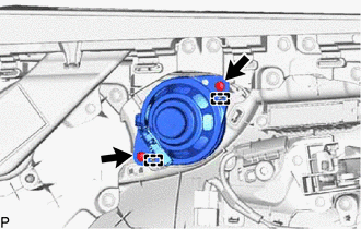
(b) Disengage the 2 guides to remove the front No. 4 speaker assembly.
READ NEXT:
 Components
COMPONENTS ILLUSTRATION *A for Side *B for Center *1 COWL SIDE TRIM BOARD *2 FRONT DOOR OPENING TRIM COVER *3 FRONT DOOR SCUFF PLATE *4 FRONT NO. 2 SPEAKER ASSEMBLY *
Inspection
INSPECTION PROCEDURE 1. INSPECT FRONT NO. 2 SPEAKER ASSEMBLY (a) With the speaker installed, check that there is no looseness or other abnormalities. (b) Check that there is no foreign matter in the s
SEE MORE:
Dtc Check / Clear
DTC CHECK / CLEAR CHECK DTC (a) Connect the Techstream to the DLC3. (b) Turn the engine switch on (IG). (c) Turn the Techstream on. (d) Enter the following menus: Body Electrical / Air Conditioner / Trouble Codes. Body Electrical > Air Conditioner > Trouble Codes (e) Check for DTCs. CLEAR DTC
Dtc Check / Clear
DTC CHECK / CLEAR CHECK FOR DTCS (a) Connect the Techstream to the DLC3. (b) Turn the power switch on (IG). (c) Turn the Techstream on. (d) Enter the following menus: Powertrain / Hybrid Control / Trouble Codes. Powertrain > Hybrid Control > Trouble Codes (e) Check the DTCs and freeze frame da
