Lexus ES: Inspection
INSPECTION
PROCEDURE
1. INSPECT FRONT NO. 2 SPEAKER ASSEMBLY
(a) With the speaker installed, check that there is no looseness or other abnormalities.
(b) Check that there is no foreign matter in the speaker, no tears on the speaker cone or other abnormalities.
(c) When there is a possibility that either the right or left speaker is malfunctioning, interchange the speakers and perform an inspection. If the malfunction disappears after interchanging the speakers, replace the malfunctioning speaker.
HINT:
Connect all connectors to the speakers when performing an inspection. If the result is not as specified, replace the speaker.
2. INSPECT FRONT NO. 3 SPEAKER ASSEMBLY (for 10 Speakers)
(a) With the speaker installed, check that there is no looseness or other abnormalities.
(b) Check that there is no foreign matter in the speaker, no tears on the speaker cone or other abnormalities.
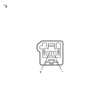
| (c) Measure the resistance of the speaker. Standard Resistance:
If the result is not as specified, replace the speaker. |
|
3. INSPECT FRONT NO. 3 SPEAKER ASSEMBLY (for 17 Speakers)
(a) With the speaker installed, check that there is no looseness or other abnormalities.
(b) Check that there is no foreign matter in the speaker, no tears on the speaker cone or other abnormalities.
(c) When there is a possibility that either the right or left speaker is malfunctioning, interchange the speakers and perform an inspection. If the malfunction disappears after interchanging the speakers, replace the malfunctioning speaker.
HINT:
Connect all connectors to the speakers when performing an inspection. If the result is not as specified, replace the speaker.
READ NEXT:
 Installation
INSTALLATION CAUTION / NOTICE / HINT HINT: for Side:
Use the same procedure for the RH side and LH side.
The following procedure is for the LH side.
PROCEDURE 1. INSTALL FRONT NO. 3 SPEAKER AS
Removal
REMOVAL CAUTION / NOTICE / HINT HINT: for Side:
Use the same procedure for the RH side and LH side.
The following procedure is for the LH side.
PROCEDURE 1. REMOVE FRONT DOOR SCUFF PLATE (for
SEE MORE:
Installation
INSTALLATION PROCEDURE 1. INSTALL ENGINE COOLANT TEMPERATURE SENSOR HINT: Perform "Inspection After Repair" after replacing the engine coolant temperature sensor. Click here (a) Apply a light coat of engine coolant to the O-ring of the engine coolant temperature sensor. (b) Install the engine c
Torque Converter And Drive Plate
InspectionINSPECTION PROCEDURE 1. INSPECT TORQUE CONVERTER ASSEMBLY (a) Inspect the one-way clutch. Press on the splines of the stator with a finger and rotate it. Check that it rotates smoothly when turned clockwise and rotates with difficulty when turned counterclockwise. Difficult
