Lexus ES: Removal
REMOVAL
CAUTION / NOTICE / HINT
The necessary procedures (adjustment, calibration, initialization, or registration) that must be performed after parts are removed and installed, or replaced during front lower No. 1 suspension arm sub-assembly removal/installation are shown below.
Necessary Procedures After Parts Removed/Installed/Replaced (for HV Model:)| Replaced Part or Performed Procedure | Necessary Procedure | Effect/Inoperative Function when Necessary Procedure not Performed | Link |
|---|---|---|---|
| *1: for LED type turn signal light | |||
| Front wheel alignment adjustment |
|
| |
| Suspension, tires, etc. (The vehicle height changes because of suspension or tire replacement.) |
|
| |
| Rear television camera assembly optical axis adjustment (Back camera position setting) | Parking Assist Monitor System | for Initialization: for Calibration: | |
| Panoramic View Monitor System | for Initialization: for Calibration: | |
| Perform headlight ECU sub-assembly LH initialization*1 | Lighting System | | |
CAUTION / NOTICE / HINT
Necessary Procedures After Parts Removed/Installed/Replaced (for Gasoline Model:)| Replaced Part or Performed Procedure | Necessary Procedure | Effect/Inoperative Function when Necessary Procedure not Performed | Link |
|---|---|---|---|
| *1: for LED Type Turn Signal Light | |||
| Front wheel alignment adjustment |
|
| |
| Suspension, tires, etc. (The vehicle height changes because of suspension or tire replacement.) |
|
| |
| Rear television camera assembly optical axis adjustment (Back camera position setting) | Parking Assist Monitor System | for Initialization: for Calibration: | |
| Panoramic View Monitor System | for Initialization: for Calibration: | |
| Perform headlight ECU sub-assembly LH initialization*1 | Lighting System | | |
HINT:
- Use the same procedure for the RH side and LH side.
- The following procedure is for the LH side.
PROCEDURE
1. REMOVE FRONT WHEEL
Click here .gif)
2. REMOVE FRONT WHEEL OPENING EXTENSION PAD LH
for A25A-FXS: Click here
for 2GR-FKS: Click here
3. REMOVE FRONT WHEEL OPENING EXTENSION PAD RH
for A25A-FXS: Click here
for 2GR-FKS: Click here
4. REMOVE NO. 1 ENGINE UNDER COVER
for A25A-FXS: Click here
for 2GR-FKS: Click here
5. REMOVE NO. 2 ENGINE UNDER COVER ASSEMBLY (for A25A-FXS)
Click here
6. REMOVE NO. 3 ENGINE UNDER COVER (for 2GR-FKS)
Click here
7. REMOVE FRONT FLOOR COVER LH
for A25A-FXS: Click here
for 2GR-FKS: Click here
8. REMOVE FRONT FENDER APRON SEAL LH
for A25A-FXS: Click here
for 2GR-FKS: Click here
9. REMOVE FRONT LOWER NO. 1 SUSPENSION ARM SUB-ASSEMBLY
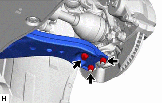
| (a) Remove the bolt and 2 nuts and separate the front lower No. 1 suspension arm sub-assembly from the front lower ball joint assembly. |
|
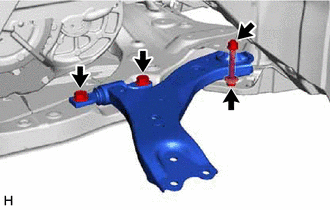
| (b) Remove the 3 bolts, nut and front lower No. 1 suspension arm sub-assembly from the front frame assembly. NOTICE: Because the nut has its own stopper, do not turn the nut. Loosen the bolt with the nut secured. |
|
(c) Remove the front lower arm bushing stopper from the front lower No. 1 suspension arm sub-assembly.
READ NEXT:
 Removal
REMOVAL CAUTION / NOTICE / HINT The necessary procedures (adjustment, calibration, initialization, or registration) that must be performed after parts are removed and installed, or replaced during fro
Installation
INSTALLATION CAUTION / NOTICE / HINT HINT:
Use the same procedure for the RH side and LH side.
The following procedure is for the LH side.
PROCEDURE 1. INSTALL FRONT LOWER NO. 1 SUSPENSION ARM
Installation
INSTALLATION CAUTION / NOTICE / HINT HINT:
Use the same procedure for the RH side and LH side.
The following procedure is for the LH side.
PROCEDURE 1. INSTALL FRONT LOWER NO. 1 SUSPENSION ARM
SEE MORE:
Removal
REMOVAL CAUTION / NOTICE / HINT The necessary procedures (adjustment, calibration, initialization or registration) that must be performed after parts are removed and installed, or replaced during transmission control cable assembly removal/installation are shown below. Necessary Procedures After Par
On-vehicle Inspection
ON-VEHICLE INSPECTION PROCEDURE 1. INSPECT FRONT LOWER BALL JOINT ASSEMBLY (a) Check for looseness. (1) Lift up the vehicle. (2) Move the front lower No. 1 suspension arm sub-assembly up and down by hand with a force of 294 N (30 kgf) or more to check that there is no looseness at the front lower
