Lexus ES: Installation
INSTALLATION
CAUTION / NOTICE / HINT
HINT:
- Use the same procedure for the RH side and LH side.
- The following procedure is for the LH side.
PROCEDURE
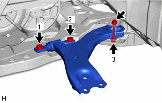
1. INSTALL FRONT LOWER NO. 1 SUSPENSION ARM SUB-ASSEMBLY
(a) Install the front lower arm bushing stopper to the front lower No. 1 suspension arm sub-assembly.
| (b) Install the front lower No. 1 suspension arm sub-assembly to the front frame assembly with the 3 bolts and nut in the order shown in the illustration. Torque: Bolt (1), (2) : 200 N·m {2039 kgf·cm, 148 ft·lbf} Bolt (3) : 135 N·m {1377 kgf·cm, 100 ft·lbf} NOTICE: Because the nut has its own stopper, do not turn the nut. Tighten the bolt with the nut secured. |
|
(c) Connect the front lower No. 1 suspension arm sub-assembly to the front lower ball joint assembly with the bolt and 2 nuts.
Torque:
92 N·m {938 kgf·cm, 68 ft·lbf}
2. INSTALL FRONT FENDER APRON SEAL LH
for A25A-FXS: Click here .gif)
for 2GR-FKS: Click here
3. INSTALL FRONT FLOOR COVER LH
for A25A-FXS: Click here
for 2GR-FKS: Click here
4. INSTALL NO. 2 ENGINE UNDER COVER ASSEMBLY (for A25A-FXS)
Click here
5. INSTALL NO. 3 ENGINE UNDER COVER (for 2GR-FKS)
Click here
6. INSTALL NO. 1 ENGINE UNDER COVER
for A25A-FXS: Click here
for 2GR-FKS: Click here
7. INSTALL FRONT WHEEL OPENING EXTENSION PAD LH
for A25A-FXS: Click here
for 2GR-FKS: Click here
8. INSTALL FRONT WHEEL OPENING EXTENSION PAD RH
for A25A-FXS: Click here
for 2GR-FKS: Click here
9. INSTALL FRONT WHEEL
Click here
10. INSPECT AND ADJUST FRONT WHEEL ALIGNMENT
Click here
11. PERFORM INITIALIZATION
for HV Model:| *1: for LED type turn signal light | |
| |
| Parking Assist Monitor System | for Initialization: for Calibration: |
| Panoramic View Monitor System | for Initialization: for Calibration: |
| Lighting System*1 | |
| *1: for LED type turn signal light | |
| |
| Parking Assist Monitor System | for Initialization: for Calibration: |
| Panoramic View Monitor System | for Initialization: for Calibration: |
| Lighting System*1 | |
READ NEXT:
 Installation
INSTALLATION CAUTION / NOTICE / HINT HINT:
Use the same procedure for the RH side and LH side.
The following procedure is for the LH side.
PROCEDURE 1. INSTALL FRONT LOWER NO. 1 SUSPENSION ARM
Components
COMPONENTS ILLUSTRATION *A w/o AVS - - *1 FRONT SHOCK ABSORBER WITH COIL SPRING *2 FRONT SPEED SENSOR *3 FRONT STABILIZER LINK ASSEMBLY *4 FRONT FLEXIBLE HOSE *5 ST
SEE MORE:
Wiper Motor Power Source Circuit
DESCRIPTION This circuit is the power source circuit for the windshield wiper motor assembly. WIRING DIAGRAM CAUTION / NOTICE / HINT NOTICE:
Inspect the fuses of circuits related to this system before performing the following procedure.
Before replacing the main body ECU (multiplex network bod
Installation
INSTALLATION PROCEDURE 1. INSTALL NO. 3 ANTENNA CORD SUB-ASSEMBLY (w/ Manual (SOS) Switch) (a) Engage the 5 clamps to install the No. 3 antenna cord sub-assembly. (b) Connect the connector. 2. INSTALL NO. 2 ANTENNA CORD SUB-ASSEMBLY HINT: Butyl tape and adhesive tape are not available as supply part
