Lexus ES: Removal
REMOVAL
CAUTION / NOTICE / HINT
The necessary procedures (adjustment, calibration, initialization, or registration) that must be performed after parts are removed and installed, or replaced during main body ECU (multiplex network body ECU) removal/installation are shown below.
Necessary Procedure After Parts Removed/Installed/Replaced (for Gasoline Model)| Replaced Part or Performed Procedure | Necessary Procedure | Effect/Inoperative Function when Necessary Procedure not Performed | Link |
|---|---|---|---|
|
*: When performing learning using the Techstream.
Click here | |||
| Disconnect cable from negative battery terminal | Perform steering sensor zero point calibration | Lane Control System (for Gasoline Model) | |
| Pre-collision System (for Gasoline Model) | |||
| Parking Support Brake System (for Gasoline Model)* | |||
| Lighting System (for Gasoline Model) | |||
| Memorize steering angle neutral point | Parking Assist Monitor System (for Gasoline Model) | | |
| Panoramic View Monitor System (for Gasoline Model) | | ||
| Initialize power trunk lid system | Power Trunk Lid System (for Gasoline Model) | | |
| Main body ECU (multiplex network body ECU) | Code registration (Smart access system with push-button start (for Start Function, Gasoline Model)) |
| |
CAUTION:
Some of these service operations affect the SRS airbag system. Read the precautionary notices concerning the SRS airbag system before servicing.
Click here .gif)
NOTICE:
- After the engine switch is turned off, the radio receiver assembly records various types of memory and settings. As a result, after turning the engine switch off, make sure to wait at least 85 seconds before disconnecting the cable from the negative (-) battery terminal. (for Audio and Visual System)
- After the engine switch is turned off, the radio receiver assembly records various types of memory and settings. As a result, after turning the engine switch off, make sure to wait at least 85 seconds before disconnecting the cable from the negative (-) battery terminal. (for Navigation System)
| Replaced Part or Performed Procedure | Necessary Procedure | Effect/Inoperative Function When Necessary Procedures are not Performed | Link |
|---|---|---|---|
|
*: When performing learning using the Techstream.
Click here | |||
| Disconnect cable from negative auxiliary battery terminal | Perform steering sensor zero point calibration | Lane Control System (for HV Model) | |
| Pre-collision System (for HV Model) | |||
| Parking Support Brake System (for HV Model)* | |||
| Lighting System (for HV Model) | |||
| Memorize steering angle neutral point | Parking Assist Monitor System (for HV Model) | | |
| Panoramic View Monitor System (for HV Model) | | ||
| Initialize power trunk lid system | Power Trunk Lid System (for HV Model) | | |
| Main body ECU (multiplex network body ECU) | Code registration (Smart access system with push-button start (for Start Function, HV Model)) |
| |
CAUTION:
Some of these service operations affect the SRS airbag system. Read the precautionary notices concerning the SRS airbag system before servicing.
Click here
NOTICE:
- After the power switch is turned off, the radio receiver assembly records various types of memory and settings. As a result, after turning the power switch off, make sure to wait at least 85 seconds before disconnecting the cable from the negative (-) auxiliary battery terminal. (for Audio and Visual System)
- After the power switch is turned off, the radio receiver assembly records various types of memory and settings. As a result, after turning the power switch off, make sure to wait at least 85 seconds before disconnecting the cable from the negative (-) auxiliary battery terminal. (for Navigation System)
PROCEDURE
1. REMOVE LOWER NO. 1 INSTRUMENT PANEL AIRBAG ASSEMBLY
Click here
2. REMOVE NO. 3 INSTRUMENT PANEL TO COWL BRACE SUB-ASSEMBLY
Click here
3. REMOVE HYBRID VEHICLE CONTROL ECU (for HV Model)
Click here
4. REMOVE INSTRUMENT PANEL JUNCTION BLOCK ASSEMBLY WITH MAIN BODY ECU
| (a) Disconnect each connector. |
|
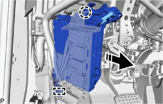
(b) Disengage the clamp.
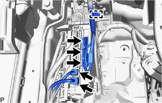
(c) Disengage the 2 claws and pull down the 2 lock levers to disconnect the 2 connectors as shown in the illustration.
.png) | Remove in this Direction |
| (d) Disconnect each connector. |
|
| (e) Remove the 2 nuts. |
|
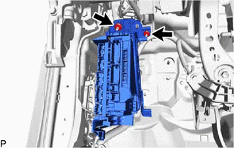
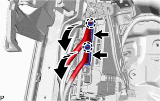
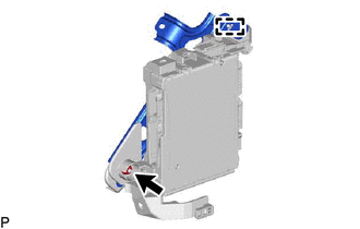
(f) Disengage the claw and guide and pull out the instrument panel junction block assembly with main body ECU.
| | Remove in this Direction |
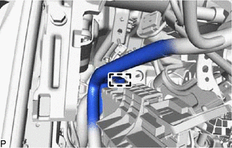
| (g) Disengage the clamp. |
|
| (h) Disengage the clamp. |
|
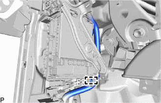
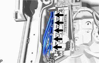
(i) Disengage the 2 claws and raise the 2 lock levers to disconnect the 2 connectors as shown in the illustration and remove the instrument panel junction block assembly with main body ECU.
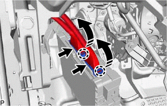
| | Remove in this Direction |
5. REMOVE WIRING HARNESS CLAMP BRACKET
| (a) Remove the nut. |
|
(b) Disengage the guide to remove the wiring harness clamp bracket.
6. REMOVE MAIN BODY ECU (MULTIPLEX NETWORK BODY ECU)
(a) Press the claw of the instrument panel junction block assembly as shown in the illustration to release the lock.
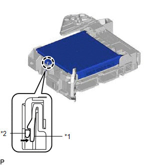
| *1 | Instrument Panel Junction Block Assembly |
| *2 | Main Body ECU (Multiplex Network Body ECU) |
 | Push in this Direction |
(b) With the instrument panel junction block assembly lock released, insert a screwdriver with its tip wrapped with protective tape horizontally between the main body ECU (multiplex network body ECU) and junction block assembly.
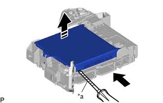
| *a | Protective Tape |
| | Insert in this Direction |
| | Remove in this Direction |
NOTICE:
- Use a screwdriver with a diameter between 5.0 mm (0.197 in.) and 6.3 mm (0.248 in.) and a length of approximately 90 mm (3.54 in.).
- Do not insert the screwdriver under the connector socket of the main body ECU (multiplex network body ECU).
(c) Using the screwdriver, carefully raise the main body ECU (multiplex network body ECU) to the position where the connector becomes disconnected.
NOTICE:
Do not twist the screwdriver to raise the main body ECU (multiplex network body ECU).
(d) Raise the main body ECU (multiplex network body ECU) as shown by the arrow (1), and then pull it out as shown by the arrow (2) in the illustration.
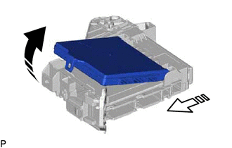
| | Remove in this Direction (1) |
 | Remove in this Direction (2) |
NOTICE:
Do not touch the main body ECU (multiplex network body ECU) connector.
READ NEXT:
 Components
COMPONENTS ILLUSTRATION *A for HV Model - - *1 HYBRID VEHICLE CONTROL ECU *2 INSTRUMENT PANEL JUNCTION BLOCK ASSEMBLY WITH MAIN BODY ECU *3 NO. 3 INSTRUMENT PANEL TO COWL BRA
SEE MORE:
Inspection
INSPECTION PROCEDURE 1. INSPECT FUEL VAPOR CONTAINMENT VALVE (FUEL TANK SOLENOID MAIN VALVE ASSEMBLY) (a) Measure the resistance according to the value(s) in the table below. Standard Resistance: Tester Connection Condition Specified Condition 1 - 2 20°C (68°F) 25 to 30 Ω If th
Vehicle Control History
VEHICLE CONTROL HISTORY NOTICE: Make sure to record any output Vehicle Control History codes before clearing them and checking the Vehicle Control History again. CHECK VEHICLE CONTROL HISTORY (ROAD SIGN ASSIST SYSTEM) (a) Connect the Techstream to the DLC3. (b) Turn the power switch on (IG). (c) Tur
