Lexus ES: Wiper and Washer Switch Circuit
DESCRIPTION
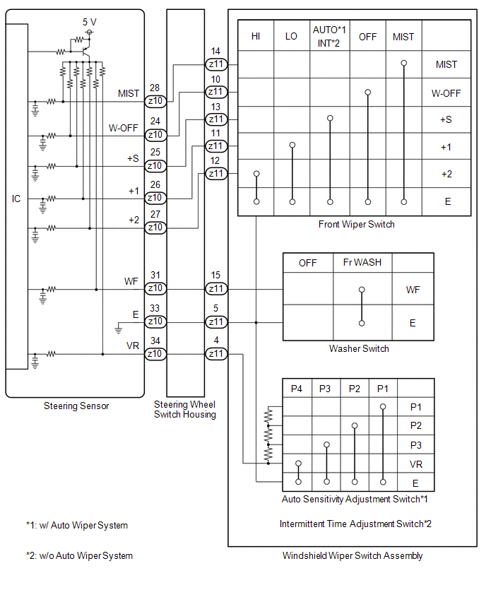
The condition of the windshield wiper switch assembly is detected and sent to the steering sensor in this circuit.
WIRING DIAGRAM
PROCEDURE
| 1. | READ VALUE USING TECHSTREAM |
(a) Connect the Techstream to the DLC3.
(b) Turn the engine switch on (IG).
(c) Turn the Techstream on.
(d) Enter the following menus: Chassis / Steering Angle Sensor / Data List.
(e) Read the Data List according to the display on the Techstream.
Chassis > Steering Angle Sensor > Data List| Tester Display | Measurement Item | Range | Normal Condition | Diagnostic Note |
|---|---|---|---|---|
| Wiper OFF Switch | Front wiper switch OFF position signal | OFF or ON | OFF: Front wiper switch not in OFF position ON: Front wiper switch in OFF position | - |
| Wiper Auto/Int Switch | Front wiper switch AUTO*2 or INT*3 position signal | OFF or ON | OFF: Front wiper switch not in AUTO*2 or INT*3 position ON: Front wiper switch in AUTO*2 or INT*3 position | - |
| Wiper Lo Switch | Front wiper switch LO position signal | OFF or ON | OFF: Front wiper switch not in LO position ON: Front wiper switch in LO position | - |
| Wiper Hi Switch | Front wiper switch HI position signal | OFF or ON | OFF: Front wiper switch not in HI position ON: Front wiper switch in HI position | - |
| Wiper Mist Switch | Front wiper switch MIST position signal | OFF or ON | OFF: Front wiper switch not in MIST position ON: Front wiper switch in MIST position | - |
| Washer Switch | Washer switch ON position signal | OFF or ON | OFF: Front washer switch not in ON position ON: Front washer switch in ON position | - |
| Intermittent Time Volume | Auto sensitivity adjustment switch condition*2 Intermittent time adjustment switch condition*3 | Shortest, Shorter, Longer or Longest | Shortest: P4 Shorter: P3 Longer: P2 Longest: P1 | *1 |
-
*1: Refer to Inspection for each position of the switch.
Click here
.gif)
- *2: w/ Auto Wiper System
- *3: w/o Auto Wiper System
| Tester Display |
|---|
| Wiper OFF Switch |
| Wiper Auto/Int Switch |
| Wiper Lo Switch |
| Wiper Hi Switch |
| Wiper Mist Switch |
| Washer Switch |
| Intermittent Time Volume |
OK:
The Techstream display changes correctly in response to the windshield wiper switch assembly operation.
| OK | .gif) | PROCEED TO NEXT SUSPECTED AREA SHOWN IN PROBLEM SYMPTOMS TABLE |
|
.gif)
| 2. | INSPECT WINDSHIELD WIPER SWITCH ASSEMBLY |
(a) Remove the windshield wiper switch assembly.
Click here
(b) Inspect the windshield wiper switch assembly.
Click here
| NG | | REPLACE WINDSHIELD WIPER SWITCH ASSEMBLY |
|
| 3. | INSPECT STEERING WHEEL SWITCH HOUSING |
(a) Remove the steering wheel switch housing.
Click here
(b) Inspect the steering wheel switch housing.
Click here
| OK | | REPLACE STEERING SENSOR |
| NG | | REPLACE STEERING WHEEL SWITCH HOUSING |
READ NEXT:
 Washer Motor Circuit
DESCRIPTION When the windshield washer motor and pump assembly receives signals from the windshield wiper switch assembly it operates to spray washer fluid from the washer nozzle sub-assemblies. WIRIN
Washer Fluid Level Warning Switch Circuit
DESCRIPTION When the washer fluid level is lower than a certain level, a warning message is displayed on the combination meter assembly. WIRING DIAGRAM PROCEDURE 1. READ VALUE USING TECHSTREAM
SEE MORE:
Control Module Communication Bus Off (U0073,U0100,U0110,U0120,U0124,U0126,U0128,U0151,U0293)
DESCRIPTION The airbag ECU assembly has a built-in yaw rate and acceleration sensor and detects the vehicle condition using 2 circuits (GL1, GL2). The skid control ECU (brake booster with master cylinder assembly) receives signals from the hybrid vehicle control ECU, steering angle sensor, certifica
Open Circuit in Main Relay 1 (C1311,C1312)
DESCRIPTION The main relay supplies power to the switching solenoid and the linear solenoid. The main relay remains on for approximately 2 minutes after the power switch is turned off and the input of brake pedal operation signals stops, and supplies power to the system to keep it ready to operate.
