Lexus ES: Removal
REMOVAL
CAUTION / NOTICE / HINT
The necessary procedures (adjustment, calibration, initialization or registration) that must be performed after parts are removed and installed, or replaced during HV floor under wire removal/installation are shown below.
Necessary Procedures After Parts Removed/Installed/Replaced| Replaced Part or Performed Procedure | Necessary Procedure | Effect/Inoperative Function when Necessary Procedure not Performed | Link |
|---|---|---|---|
|
*: When performing learning using the Techstream.
Click here | |||
| Auxiliary battery terminal is disconnected/reconnected | Perform steering sensor zero point calibration | Lane Control System | |
| Pre-collision System | |||
| Parking Support Brake System* | |||
| Lighting System | |||
| Memorize steering angle neutral point | Parking assist monitor system | | |
| Panoramic view monitor system | | ||
| Initialize power trunk lid system | Power Trunk Lid System | | |
| Inspection After Repair |
| |
CAUTION:
-
Orange wire harnesses and connectors indicate high-voltage circuits. To prevent electric shock, always follow the procedure described in the repair manual.
.png)
Click here
.gif)
-
To prevent electric shock, wear insulated gloves when working on wire harnesses and components of the high voltage system.
.png)
-
To prevent burns, do not touch the engine, exhaust manifold or other high temperature components while the engine is hot.
.png)
-
To prevent burns, do not touch the engine, exhaust pipe or other high temperature components while the engine is hot.
.png)
NOTICE:
- After the power switch is turned off, the radio receiver assembly records various types of memory and settings. As a result, after turning the power switch off, make sure to wait at least 85 seconds before disconnecting the cable from the negative (-) auxiliary battery terminal. (for Audio and Visual System)
- After the power switch is turned off, the radio receiver assembly records various types of memory and settings. As a result, after turning the power switch off, make sure to wait at least 85 seconds before disconnecting the cable from the negative (-) auxiliary battery terminal. (for Navigation System)
PROCEDURE
1. PRECAUTION
Click here
2. REMOVE SERVICE PLUG GRIP
Click here
3. DISCONNECT ENGINE ROOM MAIN WIRE
CAUTION:
Be sure to wear insulated gloves.
NOTICE:
Do not allow any foreign matter or water to enter the inverter with converter assembly.
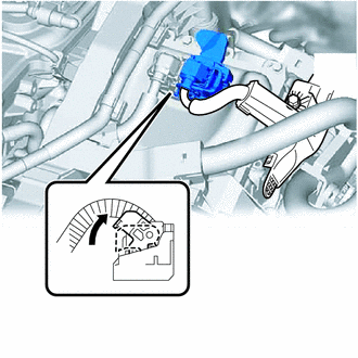
| (a) Move the lock lever while pushing the lock on the connector, and disconnect the inverter with converter assembly connector. NOTICE:
|
|
4. REMOVE CONNECTOR COVER ASSEMBLY
Click here
5. CHECK TERMINAL VOLTAGE
Click here
6. TEMPORARILY INSTALL CONNECTOR COVER ASSEMBLY
Click here
7. DISCONNECT HV FLOOR UNDER WIRE
Click here
8. REMOVE REAR SEAT CUSHION ASSEMBLY
Click here
9. REMOVE REAR SEAT CUSHION LOCK HOOK
Click here
10. REMOVE REAR DOOR SCUFF PLATE LH
Click here
11. REMOVE REAR UNDER SIDE COVER LH
Click here
12. REMOVE REAR DOOR SCUFF PLATE RH
HINT:
Use the same procedure as for the LH side.
13. REMOVE REAR UNDER SIDE COVER RH
Click here
14. REMOVE REAR UNDER COVER
Click here
15. REMOVE REAR SEAT CUSHION LEG SUB-ASSEMBLY
Click here
16. REMOVE NO. 1 HV BATTERY COVER PANEL RH
Click here
17. DISCONNECT HV FLOOR UNDER WIRE
CAUTION:
Be sure to wear insulated gloves.
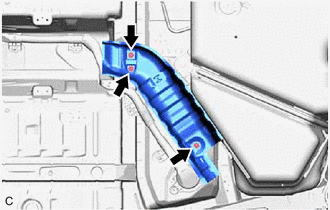
| (a) Disconnect the 2 HV battery junction block assembly connectors. NOTICE: Insulate each disconnected high-voltage connector with insulating tape. Wrap the connector from the wire harness side to the end of the connector. |
|
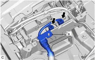
(b) Disconnect the shield ground from the HV battery.
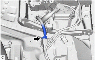
| (c) Disconnect the floor wire connector. |
|
18. REMOVE FRONT EXHAUST PIPE ASSEMBLY
Click here
19. REMOVE EXHAUST MANIFOLD
Click here
20. REMOVE NO. 1 FLOOR UNDER COVER
Click here
21. REMOVE CENTER NO. 2 FLOOR HEAT INSULATOR
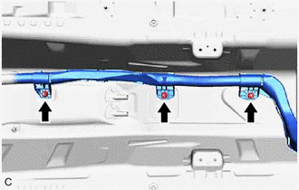
| (a) Remove the 3 nuts and center No. 2 floor heat insulator. |
|
22. DISCONNECT TRANSMISSION CONTROL CABLE ASSEMBLY
| (a) Remove the 2 nuts and disconnect the transmission control cable assembly. |
|
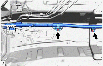
23. REMOVE HV FLOOR UNDER WIRE
CAUTION:
Be sure to wear insulated gloves.
NOTICE:
Insulate the disconnected connectors with insulating tape.
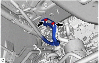
| (a) Remove the 2 nuts. |
|
(b) Remove the 2 clamps.
NOTICE:
If the clamps are removed forcibly, the stud bolts may be damaged.
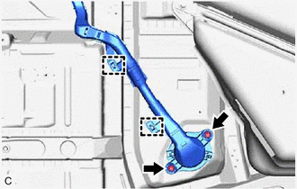
| (c) Disengage the grommet and pull out the HV floor under wire from the floor panel hole. |
|
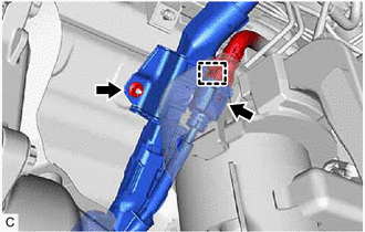
| (d) Remove the 3 nuts. |
|
| (e) Remove the 2 nuts and clamp. NOTICE: If the clamp is removed forcibly, the stud bolt may be damaged. |
|
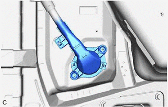
| (f) Disengage the clamp. |
|
(g) Disconnect the HV floor under wire connector.
(h) Remove the nut and HV floor under wire.
READ NEXT:
 Installation
INSTALLATION PROCEDURE 1. INSTALL HV FLOOR UNDER WIRE CAUTION: Be sure to wear insulated gloves. (a) Insert the HV floor under wire into the floor panel hole and engage the grommet.
Installation
INSTALLATION PROCEDURE 1. INSTALL FLOOR UNDER WIRE CAUTION: Be sure to wear insulated gloves. (a) Insert the HV floor under wire into the floor panel hole and engage the grommet. (b)
SEE MORE:
System Diagram
SYSTEM DIAGRAM Communication Table Transmitting ECU Receiving ECU Signal Communication Method Multiplex Network Master Switch Assembly Power Window Regulator Motor Assembly (for Driver Door) Power window auto up and down signal LIN
Power Window Regulator Motor Assembly (
Reassembly
REASSEMBLY CAUTION / NOTICE / HINT HINT:
Use the same procedure for the RH side and LH side.
The following procedure is for the LH side.
PROCEDURE 1. INSTALL VISOR COVER ASSEMBLY Click here 2. INSTALL OUTER MIRROR UPPER COVER Click here 3. INSTALL OUTER MIRROR LOWER COVER Click here 4.
