Lexus ES: Removal
REMOVAL
CAUTION / NOTICE / HINT
The necessary procedures (adjustment, calibration, initialization or registration) that must be performed after parts are removed and installed, or replaced during intake manifold removal/installation are shown below.
Necessary Procedures After Parts Removed/Installed/Replaced| Replaced Part or Performed Procedure | Necessary Procedure | Effect/Inoperative Function when Necessary Procedure not Performed | Link |
|---|---|---|---|
| Inspection After Repair |
| |
NOTICE:
This procedure includes the removal of small-head bolts. Refer to Small-Head Bolts of Basic Repair Hint to identify the small-head bolts.
Click here .gif)
PROCEDURE
1. REMOVE THROTTLE BODY WITH MOTOR ASSEMBLY
Click here
2. REMOVE EGR VALVE ASSEMBLY
Click here
3. REMOVE E.F.I. VACUUM SENSOR ASSEMBLY (MANIFOLD ABSOLUTE PRESSURE SENSOR)
Click here
4. REMOVE PURGE VALVE (PURGE VSV)
Click here
5. DISCONNECT ENGINE WIRE
| (a) Disconnect the No. 5 engine wire connector. |
|
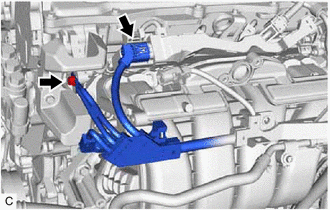
(b) Remove the bolt and disconnect the engine wire from the cylinder head sub-assembly.
| (c) Remove the bolt. |
|
(d) Disengage the wire harness clamp and disconnect the engine wire from the intake manifold.
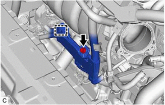
6. DISCONNECT NO. 3 WATER BY-PASS PIPE
| (a) Slide the clip and disconnect the No. 5 water by-pass hose from the No. 3 water by-pass pipe. |
|
(b) Using an 8 mm socket wrench, remove the bolt and disconnect the No. 3 water by-pass pipe from the intake manifold.
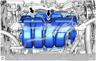
7. REMOVE NO. 2 WATER BY-PASS PIPE
| (a) Disengage the wire harness clamp and disconnect the HV air conditioning wire. |
|
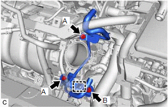
(b) Using an 8 mm socket wrench, remove the 2 bolts (A) and separate the No. 2 water by-pass pipe from the intake manifold.
(c) Remove the bolt (B) and No. 2 water by-pass pipe from the cylinder block sub-assembly.
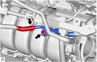
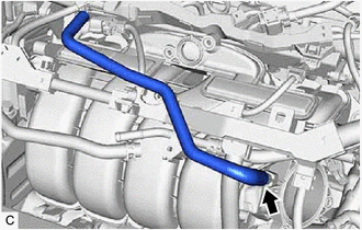
8. REMOVE NO. 2 FUEL VAPOR FEED HOSE
| (a) Remove the No. 2 fuel vapor feed hose from the intake manifold. |
|
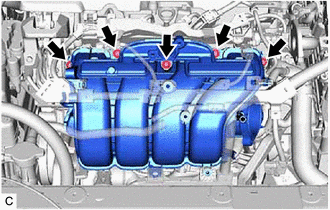
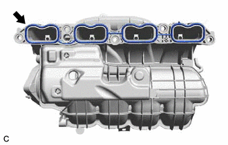
9. REMOVE INTAKE MANIFOLD
| (a) w/o Stud Bolt: (1) Remove the 5 bolts and intake manifold from the cylinder head sub-assembly. |
|
(b) w/ Stud Bolt:
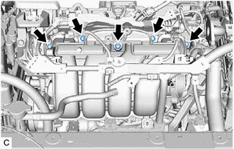
(1) Remove the 3 bolts and 2 nuts.
| (2) Using an E8 "TORX" socket wrench, remove the 2 stud bolts and intake manifold from the cylinder head sub-assembly. |
|
10. REMOVE NO. 1 INTAKE MANIFOLD TO HEAD GASKET
| (a) Remove the No. 1 intake manifold to head gasket from the intake manifold. |
|
11. REMOVE NO. 1 ENGINE COVER
| (a) Remove the clip and No. 1 engine cover. |
|
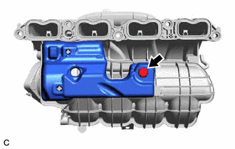
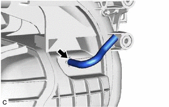
12. REMOVE VACUUM HOSE
| (a) Remove the vacuum hose from the intake manifold. |
|
READ NEXT:
 Installation
INSTALLATION CAUTION / NOTICE / HINT NOTICE: This procedure includes the installation of small-head bolts. Refer to Small-Head Bolts of Basic Repair Hint to identify the small-head bolts. Click here
Intake System
On-vehicle InspectionON-VEHICLE INSPECTION CAUTION / NOTICE / HINT The necessary procedures (adjustment, calibration, initialization or registration) that must be performed after parts are removed an
SEE MORE:
How To Proceed With Troubleshooting
CAUTION / NOTICE / HINT HINT:
Before performing troubleshooting for the dynamic radar cruise control system, perform troubleshooting for the pre-collision system.
Click here
*: Use the Techstream.
PROCEDURE 1. VEHICLE BROUGHT TO WORKSHOP
NEXT 2. PRE-CHECK
Components
COMPONENTS ILLUSTRATION *1 BODY ROCKER PANEL MOULDING ASSEMBLY *2 NO. 2 ROCKER PANEL MOULDING PROTECTOR *3 ROCKER PANEL MOULDING COVER *4 CLIP ● Non-reusable part - - ILLUSTRATION *1 NO. 4 ROCKER PANEL MOULDING PROTECTOR *2 NO. 5 ROCKER PANEL MOULDING PRO
