Lexus ES: Installation
INSTALLATION
CAUTION / NOTICE / HINT
NOTICE:
This procedure includes the installation of small-head bolts. Refer to Small-Head Bolts of Basic Repair Hint to identify the small-head bolts.
Click here .gif)
PROCEDURE
1. INSTALL VACUUM HOSE
(a) Install the vacuum hose to the intake manifold.
2. INSTALL NO. 1 ENGINE COVER
(a) Install the No. 1 engine cover with the clip.
3. INSTALL NO. 1 INTAKE MANIFOLD TO HEAD GASKET
(a) Install a new No. 1 intake manifold to head gasket to the intake manifold.
4. INSTALL INTAKE MANIFOLD
(a) w/o Stud Bolt:
| (1) Temporarily install the intake manifold to the cylinder head sub-assembly with the 5 bolts. |
|
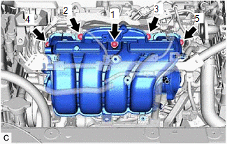
(2) Tighten the 5 bolts in the order shown in the illustration.
Torque:
24 N·m {245 kgf·cm, 18 ft·lbf}
(b) w/ Stud Bolt:
| (1) Temporarily install the intake manifold to the cylinder head sub-assembly. |
|
.png)
(2) Using an E8 "TORX" socket wrench, install the 2 stud bolts.
Torque:
6.5 N·m {66 kgf·cm, 58 in·lbf}
| (3) Temporarily install the 3 bolts and 2 nuts. |
|
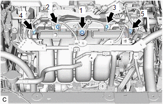
(4) Tighten the 3 bolts and 2 nuts in the order shown in the illustration.
Torque:
24 N·m {245 kgf·cm, 18 ft·lbf}
5. INSTALL NO. 2 FUEL VAPOR FEED HOSE
(a) Install the No. 2 fuel vapor feed hose to the intake manifold.
6. INSTALL NO. 2 WATER BY-PASS PIPE
| (a) Temporarily install the No. 2 water by-pass pipe to the cylinder block sub-assembly with the bolt (B). |
|
.png)
(b) Using an 8 mm socket wrench, temporarily install the No. 2 water by-pass pipe to the intake manifold with the 2 bolts (A).
(c) Tighten the bolt (B).
Torque:
21 N·m {214 kgf·cm, 15 ft·lbf}
(d) Using the 8 mm socket wrench, tighten the 2 bolts (A).
Torque:
10 N·m {102 kgf·cm, 7 ft·lbf}
(e) Engage the wire harness clamp to connect the HV air conditioning wire.
7. CONNECT NO. 3 WATER BY-PASS PIPE
(a) Using an 8 mm socket wrench, connect the No. 3 water by-pass pipe to the intake manifold with the bolt.
Torque:
10 N·m {102 kgf·cm, 7 ft·lbf}
(b) Connect the No. 5 water by-pass hose to the No. 3 water by-pass pipe and slide the clip to secure it.
8. CONNECT ENGINE WIRE
| (a) Engage the wire harness clamp to connect the engine wire to the intake manifold. |
|
.png)
(b) Install the bolt.
Torque:
10 N·m {102 kgf·cm, 7 ft·lbf}
| (c) Connect the engine wire to the cylinder head sub-assembly with the bolt. Torque: 10 N·m {102 kgf·cm, 7 ft·lbf} |
|
.png)
(d) Connect the No. 5 engine wire connector.
9. INSTALL PURGE VALVE (PURGE VSV)
Click here
10. INSTALL E.F.I. VACUUM SENSOR ASSEMBLY (MANIFOLD ABSOLUTE PRESSURE SENSOR)
Click here
11. INSTALL EGR VALVE ASSEMBLY
Click here
12. INSTALL THROTTLE BODY WITH MOTOR ASSEMBLY
Click here
READ NEXT:
 Intake System
On-vehicle InspectionON-VEHICLE INSPECTION CAUTION / NOTICE / HINT The necessary procedures (adjustment, calibration, initialization or registration) that must be performed after parts are removed an
Lubrication System
On-vehicle InspectionON-VEHICLE INSPECTION PROCEDURE 1. CHECK ENGINE OIL LEVEL (a) Connect the Techstream to the DLC3. (b) Turn the power switch on (IG). (c) Turn the Techstream on. (d) Put the engin
SEE MORE:
Components
COMPONENTS ILLUSTRATION *1 VVT SENSOR (for Intake Side of Bank 1) *2 VVT SENSOR (for Exhaust Side of Bank 1) *3 VVT SENSOR (for Intake Side of Bank 2) *4 VVT SENSOR (for Exhaust Side of Bank 2) N*m (kgf*cm, ft.*lbf): Specified torque Adhesive 1324 ★ Precoated
Components
COMPONENTS ILLUSTRATION *1 BODY ROCKER PANEL MOULDING ASSEMBLY *2 NO. 2 ROCKER PANEL MOULDING PROTECTOR *3 ROCKER PANEL MOULDING COVER *4 CLIP ● Non-reusable part - - ILLUSTRATION *1 NO. 4 ROCKER PANEL MOULDING PROTECTOR *2 NO. 5 ROCKER PANEL MOULDING PRO
