Lexus ES: Intake System
On-vehicle Inspection
ON-VEHICLE INSPECTION
CAUTION / NOTICE / HINT
The necessary procedures (adjustment, calibration, initialization or registration) that must be performed after parts are removed and installed, or replaced when repairing air leaks in the intake system are shown below.
Necessary Procedures After Parts Removed/Installed/Replaced| Replaced Part or Performed Procedure | Necessary Procedure | Effect/Inoperative Function when Necessary Procedure not Performed | Link |
|---|---|---|---|
| Air leaks from intake system is repaired | Inspection After Repair |
| |
PROCEDURE
1. INSPECT INTAKE SYSTEM
CAUTION:
To prevent injury due to contact with an operating cooling fan, keep your hands and clothing away from the cooling fans when working in the engine compartment with the engine running or the power switch on (IG).
.png)
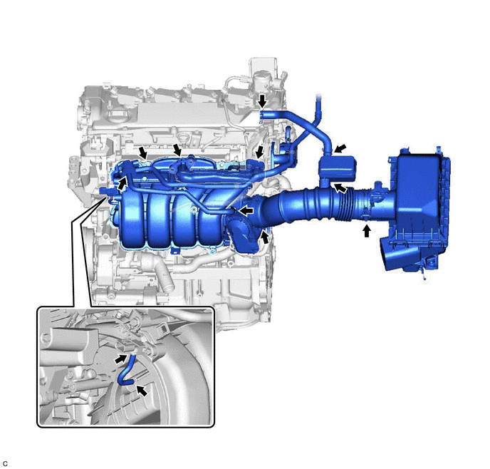
(a) Check that there are no vacuum leaks at the points shown in the illustration.
HINT:
Perform "Inspection After Repair" after repairing vacuum leaks in the intake system.
Click here .gif)
2. PERFORM INITIALIZATION
(a) Perform "Inspection After Repair" after repairing vacuum leaks in the intake system.
Click here
READ NEXT:
 Lubrication System
On-vehicle InspectionON-VEHICLE INSPECTION PROCEDURE 1. CHECK ENGINE OIL LEVEL (a) Connect the Techstream to the DLC3. (b) Turn the power switch on (IG). (c) Turn the Techstream on. (d) Put the engin
Oil And Oil Filter
ComponentsCOMPONENTS ILLUSTRATION *1 CENTER NO. 4 ENGINE UNDER COVER - - ILLUSTRATION *1 OIL FILTER SUB-ASSEMBLY *2 OIL FILLER CAP SUB-ASSEMBLY *3 GASKET *4 OIL PAN D
SEE MORE:
System Description
SYSTEM DESCRIPTION POWER WINDOW CONTROL SYSTEM DESCRIPTION (a) The power window control system controls the power window operation using the power window regulator motor assemblies. The main controls of this system are the multiplex network master switch assembly (mounted on the driver door), power
Cursor or Map Rotates when Vehicle Stopped
PROCEDURE 1. CHECK CONDITION (a) Check with the customer if the vehicle has been turned by a turntable. OK: Vehicle has not been turned by a turntable. HINT: If the vehicle is turned on a turntable with the engine switch on (IG), the system may store the angular velocity. As a result, t
