Lexus ES: Removal
REMOVAL
CAUTION / NOTICE / HINT
The necessary procedures (adjustment, calibration, initialization or registration) that must be performed after parts are removed and installed, or replaced during exhaust manifold (TWC: Front Catalyst) removal/installation are shown below.
Necessary Procedures After Parts Removed/Installed/Replaced| Replaced Part or Performed Procedure | Necessary Procedure | Effect/Inoperative Function when Necessary Procedure not Performed | Link |
|---|---|---|---|
| Inspection After Repair |
| |
CAUTION:
-
To prevent burns, do not touch the engine, exhaust manifold or other high temperature components while the engine is hot.
.png)
-
To prevent burns, do not touch the engine, exhaust pipe or other high temperature components while the engine is hot.
.png)
PROCEDURE
1. REMOVE FRONT FLOOR COVER LH
Click here .gif)
2. REMOVE FRONT FLOOR COVER RH
Click here
3. REMOVE FRONT CENTER FLOOR BRACE
Click here
4. REMOVE CENTER FLOOR CROSSMEMBER BRACE
Click here
5. REMOVE FRONT EXHAUST PIPE ASSEMBLY (TWC: Rear Catalyst)
CAUTION:
To prevent burns, do not touch the engine, exhaust pipe or other high temperature components while the engine is hot.
| (a) Disengage the wire harness clamp. |
|
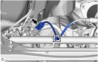
(b) Disconnect the air fuel ratio sensor (for sensor 2) connector.
| (c) Remove the 2 bolts, 2 nuts and disconnect the front exhaust pipe assembly (TWC: Rear Catalyst) from the exhaust manifold (TWC: Front Catalyst) and center exhaust pipe assembly. |
|
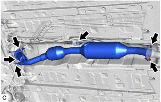
(d) Remove the front exhaust pipe assembly (TWC: Rear Catalyst) from the 2 exhaust pipe supports.
(e) Remove the 2 gaskets from the front exhaust pipe assembly (TWC: Rear Catalyst).
6. REMOVE FRONT LOWER NO. 1 FLOOR HEAT INSULATOR
Click here
7. REMOVE FRONT WHEEL OPENING EXTENSION PAD LH
Click here
8. REMOVE FRONT WHEEL OPENING EXTENSION PAD RH
Click here
9. REMOVE NO. 1 ENGINE UNDER COVER
Click here
10. REMOVE NO. 2 ENGINE UNDER COVER ASSEMBLY
Click here
11. REMOVE COWL TOP VENTILATOR LOUVER SUB-ASSEMBLY
Click here
12. REMOVE FRONT CENTER UPPER SUSPENSION BRACE SUB-ASSEMBLY
Click here
13. REMOVE AIR FUEL RATIO SENSOR (for Sensor 1)
Click here
14. REMOVE WIRE HARNESS CLAMP BRACKET
CAUTION:
To prevent burns, do not touch the engine, exhaust manifold or other high temperature components while the engine is hot.
| (a) Remove the bolt and wire harness clamp bracket. |
|
.png)
15. SEPARATE NO. 1 EXHAUST MANIFOLD HEAT INSULATOR
CAUTION:
To prevent burns, do not touch the engine, exhaust manifold or other high temperature components while the engine is hot.
(a) Type A:
| (1) Remove the 5 bolts and separate the No. 1 exhaust manifold heat insulator from the exhaust manifold (TWC: Front Catalyst). |
|
(b) Type B:
| (1) Remove the 3 bolts and separate the No. 1 exhaust manifold heat insulator from the exhaust manifold. |
|
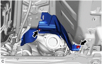
16. SEPARATE NO. 1 UPPER FRONT FLOOR HEAT INSULATOR
CAUTION:
To prevent burns, do not touch the engine, exhaust manifold or other high temperature components while the engine is hot.
| (a) Remove the 2 nuts and separate the No. 1 upper front floor heat insulator from the vehicle body. |
|
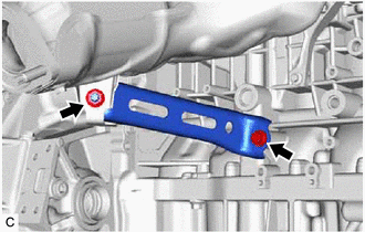
17. REMOVE MANIFOLD STAY
CAUTION:
To prevent burns, do not touch the engine, exhaust manifold or other high temperature components while the engine is hot.
| (a) Remove the bolt, nut and manifold stay from the exhaust manifold (TWC: Front Catalyst) and cylinder block sub-assembly. |
|
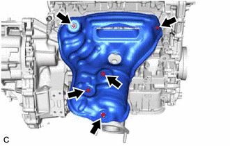
18. REMOVE EXHAUST MANIFOLD (TWC: Front Catalyst)
CAUTION:
To prevent burns, do not touch the engine, exhaust manifold or other high temperature components while the engine is hot.
| (a) Using a 12 mm deep socket wrench, remove the 7 nuts and separate the exhaust manifold (TWC: Front Catalyst) from the cylinder head sub-assembly. |
|
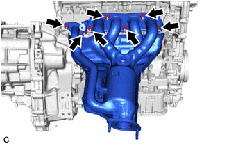
(b) Remove the No. 1 upper front floor heat insulator, No. 1 exhaust manifold heat insulator and exhaust manifold (TWC: Front Catalyst).
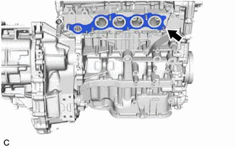
| (c) Remove the exhaust manifold to head gasket from the cylinder head sub-assembly. |
|
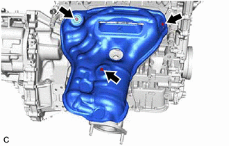
19. REMOVE NO. 2 EXHAUST MANIFOLD HEAT INSULATOR
| (a) Type A: (1) Remove the 6 bolts and No. 2 exhaust manifold heat insulator from the exhaust manifold (TWC: Front Catalyst). |
|
.png)
| (b) Type B: (1) Remove the 3 bolts and No. 2 exhaust manifold heat insulator from the exhaust manifold. |
|
.png)
READ NEXT:
 Installation
INSTALLATION PROCEDURE 1. INSTALL NO. 2 EXHAUST MANIFOLD HEAT INSULATOR (a) Type A: (1) Install the No. 2 exhaust manifold heat insulator to the exhaust manifold (TWC: Front Catalyst) with the 6 bolts
Components
COMPONENTS ILLUSTRATION *A Type A *B Type B *1 FRONT FLOOR COVER RH - - N*m (kgf*cm, ft.*lbf): Specified torque - - ILLUSTRATION *A Type A *B Type B *1
SEE MORE:
O2 Sensor Slow Response - Rich to Lean Bank 1 Sensor 1 (P014C00,P014D00,P015A00,P015B00)
DESCRIPTION Refer to DTC P003012. Click here HINT: Although the DTC titles say O2 sensor, these DTCs relate to the air fuel ratio sensor (sensor 1). DTC No. Detection Item DTC Detection Condition Trouble Area MIL Memory Note P014C00 O2 Sensor Slow Response - Rich to Lean Bank
Camera Position Adjustment Incomplete (C1697)
DESCRIPTION This DTC is stored when the parking assist ECU judges that the camera initial setting has not been memorized (camera view adjustment is incomplete). DTC No. Detection Item DTC Detection Condition Trouble Area C1697 Camera Position Adjustment Incomplete Camera initial set
