Lexus ES: Components
COMPONENTS
ILLUSTRATION
.png)
| *A | Type A | *B | Type B |
| *1 | FRONT FLOOR COVER RH | - | - |
.png) | N*m (kgf*cm, ft.*lbf): Specified torque | - | - |
ILLUSTRATION
.png)
| *A | Type A | *B | Type B |
| *1 | FRONT FLOOR COVER LH | - | - |
| | N*m (kgf*cm, ft.*lbf): Specified torque | - | - |
ILLUSTRATION
.png)
| *1 | CENTER FLOOR CROSSMEMBER BRACE | *2 | FRONT CENTER FLOOR BRACE |
| | N*m (kgf*cm, ft.*lbf): Specified torque | - | - |
ILLUSTRATION
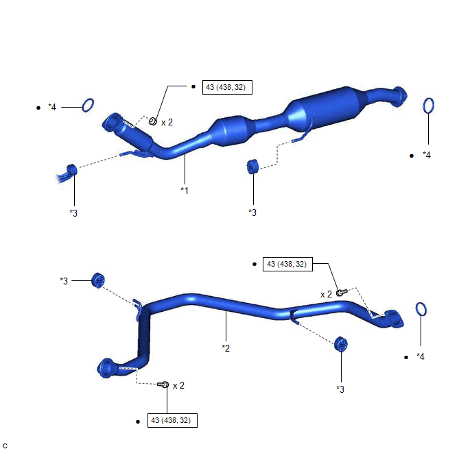
| *1 | FRONT EXHAUST PIPE ASSEMBLY (TWC: Rear Catalyst) | *2 | CENTER EXHAUST PIPE ASSEMBLY |
| *3 | EXHAUST PIPE SUPPORT | *4 | GASKET |
| | N*m (kgf*cm, ft.*lbf): Specified torque | ● | Non-reusable part |
ILLUSTRATION
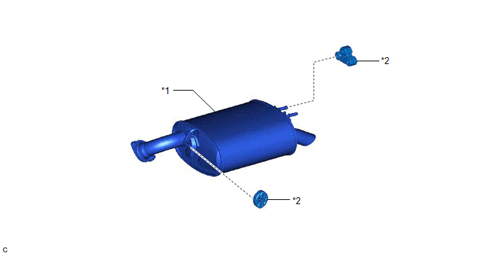
| *1 | TAIL EXHAUST PIPE ASSEMBLY LH | *2 | EXHAUST PIPE SUPPORT |
READ NEXT:
 Removal
REMOVAL CAUTION / NOTICE / HINT The necessary procedures (adjustment, calibration, initialization or registration) that must be performed after parts are removed and installed, or replaced during fron
Installation
INSTALLATION PROCEDURE 1. INSTALL FRONT EXHAUST PIPE ASSEMBLY (TWC: Rear Catalyst) (a) Install a new gasket to the front exhaust pipe assembly (TWC: Rear Catalyst). (b) Connect the front exhaust pipe
SEE MORE:
Dtc Check / Clear
DTC CHECK / CLEAR CHECK DTC (a) Turn the power switch off. (b) Connect the Techstream to the DLC3. (c) Turn the power switch on (IG). (d) Turn the Techstream on. (e) Enter the following menus: Body Electrical / Tilt & Telescopic / Trouble Codes. Body Electrical > Tilt&Telescopic > Trou
Problem Symptoms Table
PROBLEM SYMPTOMS TABLE HINT: Use the table below to help determine the cause of problem symptoms. If multiple suspected areas are listed, the potential causes of the symptoms are listed in order of probability in the "Suspected Area" column of the table. Check each symptom by checking the suspected
© 2016-2026 Copyright www.lexguide.net
