Lexus ES: Installation
INSTALLATION
PROCEDURE
1. INSTALL NO. 2 EXHAUST MANIFOLD HEAT INSULATOR
(a) Type A:
(1) Install the No. 2 exhaust manifold heat insulator to the exhaust manifold (TWC: Front Catalyst) with the 6 bolts.
Torque:
11 N·m {112 kgf·cm, 8 ft·lbf}
(b) Type B:
(1) Install the No. 2 exhaust manifold heat insulator to the exhaust manifold with the 3 bolts.
Torque:
11 N·m {112 kgf·cm, 8 ft·lbf}
2. INSTALL EXHAUST MANIFOLD (TWC: Front Catalyst)
(a) Install a new exhaust manifold to head gasket to the cylinder head sub-assembly.
(b) Temporarily install the exhaust manifold (TWC: Front Catalyst), No. 1 exhaust manifold heat insulator and No. 1 upper front floor heat insulator.
HINT:
At this time, do not install the parts with bolts or nuts.
| (c) Using a 12 mm deep socket wrench, temporarily install the exhaust manifold (TWC: Front Catalyst) to the cylinder head sub-assembly with 7 new nuts. |
|
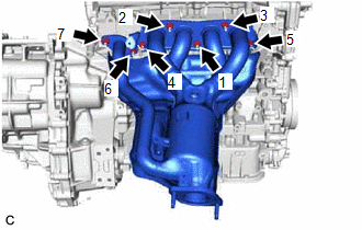
(d) Using the 12 mm deep socket wrench, tighten the 7 nuts in the order shown in the illustration.
Torque:
26 N·m {265 kgf·cm, 19 ft·lbf}
3. INSTALL MANIFOLD STAY
| (a) Temporarily install the manifold stay to the exhaust manifold (TWC: Front Catalyst) and cylinder block sub-assembly with the bolt and nut. |
|
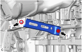
(b) Tighten the bolt and nut in the order shown in the illustration.
Torque:
43 N·m {438 kgf·cm, 32 ft·lbf}
4. INSTALL NO. 1 EXHAUST MANIFOLD HEAT INSULATOR
(a) Type A:
| (1) Using a 10 mm union nut wrench, install the No. 1 exhaust manifold heat insulator to the exhaust manifold (TWC: Front Catalyst) with the 5 bolts. Torque: Specified tightening torque : 10 N·m {102 kgf·cm, 7 ft·lbf} HINT:
|
|
(b) Type B:
(1) Install the No. 1 exhaust manifold heat insulator to the exhaust manifold with the 3 bolts.
Torque:
10 N·m {102 kgf·cm, 7 ft·lbf}
5. INSTALL NO. 1 UPPER FRONT FLOOR HEAT INSULATOR
| (a) Using a 10 mm union nut wrench, install the No. 1 upper front floor heat insulator to the vehicle body with the 2 nuts. Torque: Specified tightening torque : 4.9 N·m {50 kgf·cm, 43 in·lbf} HINT:
|
|
6. INSTALL WIRE HARNESS CLAMP BRACKET
(a) Install the wire harness clamp bracket with the bolt.
Torque:
13 N·m {133 kgf·cm, 10 ft·lbf}
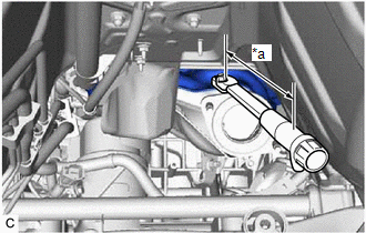
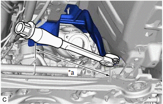
7. INSTALL AIR FUEL RATIO SENSOR (for Sensor 1)
Click here .gif)
8. INSTALL FRONT CENTER UPPER SUSPENSION BRACE SUB-ASSEMBLY
Click here
9. INSTALL COWL TOP VENTILATOR LOUVER SUB-ASSEMBLY
Click here
10. INSTALL FRONT LOWER NO. 1 FLOOR HEAT INSULATOR
Click here
11. INSTALL FRONT EXHAUST PIPE ASSEMBLY (TWC: Rear Catalyst)
(a) Install 2 new gaskets to the front exhaust pipe assembly (TWC: Rear Catalyst).
(b) Connect the front exhaust pipe assembly (TWC: Rear Catalyst) to the 2 exhaust pipe supports.
(c) Install the front exhaust pipe assembly (TWC: Rear Catalyst) to the exhaust manifold (TWC: Front Catalyst) and center exhaust pipe assembly with 2 new bolts and 2 new nuts.
Torque:
43 N·m {438 kgf·cm, 32 ft·lbf}
(d) Engage the wire harness clamp.
(e) Connect the air fuel ratio sensor (for sensor 2) connector.
12. INSTALL CENTER FLOOR CROSSMEMBER BRACE
Click here
13. INSTALL FRONT CENTER FLOOR BRACE
Click here
14. INSTALL FRONT FLOOR COVER LH
Click here
15. INSTALL FRONT FLOOR COVER RH
Click here
16. INSPECT FOR EXHAUST GAS LEAK
Click here
17. INSTALL NO. 2 ENGINE UNDER COVER ASSEMBLY
Click here
18. INSTALL NO. 1 ENGINE UNDER COVER
Click here
19. INSTALL FRONT WHEEL OPENING EXTENSION PAD LH
Click here
20. INSTALL FRONT WHEEL OPENING EXTENSION PAD RH
Click here
READ NEXT:
 Components
COMPONENTS ILLUSTRATION *A Type A *B Type B *1 FRONT FLOOR COVER RH - - N*m (kgf*cm, ft.*lbf): Specified torque - - ILLUSTRATION *A Type A *B Type B *1
Removal
REMOVAL CAUTION / NOTICE / HINT The necessary procedures (adjustment, calibration, initialization or registration) that must be performed after parts are removed and installed, or replaced during fron
SEE MORE:
Removal
REMOVAL PROCEDURE 1. REMOVE FRONT WHEEL OPENING EXTENSION PAD LH Click here 2. REMOVE FRONT WHEEL OPENING EXTENSION PAD RH Click here 3. REMOVE NO. 1 ENGINE UNDER COVER Click here 4. DRAIN COOLANT (for Inverter) Click here 5. REMOVE INVERTER WATER PUMP ASSEMBLY (a) Disconnect the in
Removal
REMOVAL CAUTION / NOTICE / HINT The necessary procedures (adjustment, calibration, initialization, or registration) that must be performed after parts are removed and installed, or replaced during rear bumper assembly removal/installation are shown below. Necessary Procedure After Parts Removed/Inst
