Lexus ES: O2 Sensor Slow Response - Rich to Lean Bank 1 Sensor 1 (P014C00,P014D00,P015A00,P015B00)
DESCRIPTION
Refer to DTC P003012.
Click here .gif)
HINT:
Although the DTC titles say O2 sensor, these DTCs relate to the air fuel ratio sensor (sensor 1).
| DTC No. | Detection Item | DTC Detection Condition | Trouble Area | MIL | Memory | Note |
|---|---|---|---|---|---|---|
| P014C00 | O2 Sensor Slow Response - Rich to Lean Bank 1 Sensor 1 | The rich to lean response rate deterioration level* value is standard or less (2 trip detection logic). |
| Comes on | DTC stored | SAE Code: P014C |
| P014D00 | O2 Sensor Slow Response - Lean to Rich Bank 1 Sensor 1 | The lean to rich response rate deterioration level* value is standard or more (2 trip detection logic). |
| Comes on | DTC stored | SAE Code: P014D |
| P015A00 | O2 Sensor Delayed Response - Rich to Lean Bank 1 Sensor 1 | The rich to lean delay level* value is standard or more (2 trip detection logic). |
| Comes on | DTC stored | SAE Code: P015A |
| P015B00 | O2 Sensor Delayed Response - Lean to Rich Bank 1 Sensor 1 | The lean to rich delay level* value is standard or more (2 trip detection logic). |
| Comes on | DTC stored | SAE Code: P015B |
*: Calculated by ECM based on the air fuel ratio sensor (sensor 1) output.
MONITOR DESCRIPTION
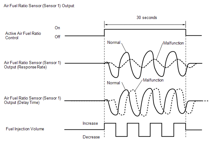
After the engine has been warmed up, the ECM carries out air fuel ratio feedback control and maintains the air fuel ratio at the theoretical ratio. In addition, after all the preconditions have been met, active air fuel ratio control is performed for approximately 30 seconds. During active air fuel ratio control, the ECM measures the response of the air fuel ratio sensor (sensor 1) by increasing or decreasing a specific injection quantity based on the theoretical air fuel ratio learned during normal air fuel control. The ECM determines whether there is an air fuel ratio sensor (sensor 1) malfunction at the mid-point of active air fuel ratio control.
If the response of the air fuel ratio sensor (sensor 1) has decreased, DTC P014C00 and P014D00 are output.
If the air fuel ratio sensor (sensor 1) output timing is delayed, DTC P015A00 and P015B00 are output.
MONITOR STRATEGY
| Related DTCs | P014C: Air fuel ratio sensor (sensor 1) response rate (rich to lean response rate) P014D: Air fuel ratio sensor (sensor 1) response rate (lean to rich response rate) P015A: Air fuel ratio sensor (sensor 1) response rate (rich to lean delay) P015B: Air fuel ratio sensor (sensor 1) response rate (lean to rich delay) |
| Required Sensors/Components (Main) | Air fuel ratio sensor (sensor 1) |
| Required Sensors/Components (Related) | Crankshaft position sensor |
| Frequency of Operation | Once per driving cycle |
| Duration | 10 to 15 seconds |
| MIL Operation | 2 driving cycles |
| Sequence of Operation | None |
TYPICAL ENABLING CONDITIONS
| Monitor runs whenever the following DTCs are not stored | P0010, P1360, P1362, P1364, P1366, P2614 (Motor drive VVT system control module) P0011 (VVT system - advance) P0012 (VVT system - retard) P0013 (Exhaust VVT oil control solenoid) P0014 (Exhaust VVT system - advance) P0015 (Exhaust VVT system - retard) P0016 (VVT system - misalignment) P0017 (Exhaust VVT system - misalignment) P0031, P0032, P101D (Air fuel ratio sensor (sensor 1) heater) P0037, P0038, P102D (Air fuel ratio sensor (sensor 2) heater) P0087, P0088, P0191, P0192, P0193 (Fuel pressure sensor (for high pressure side)) P0101, P0102, P0103 (Mass air flow meter) P0106, P0107, P0108 (Manifold absolute pressure) P0111, P0112, P0113 (Intake air temperature sensor) P0116, P0117, P0118 (Engine coolant temperature sensor) P0121, P0122, P0123, P0222, P0223, P2135 (Throttle position sensor) P0125 (Insufficient coolant temperature for closed loop fuel control) P0128 (Thermostat) P0136, P013A, P2270, P2271, P22AB, P22AC, P22AD, P22B3, P22B4 (Air fuel ratio sensor (sensor 2)) P0171, P0172 (Fuel system) P0201, P0202, P0203, P0204, P062D, P21CF, P21D0, P21D1, P21D2 (Fuel injector) P0300, P0301, P0302, P0303, P0304 (Misfire) P0327, P0328 (Knock control sensor) P0335, P0337, P0338 (Crankshaft position sensor) P0340, P0342, P0343 (Camshaft position sensor) P0365, P0367, P0368 (Exhaust camshaft position sensor) P0401 (EGR system (closed)) P0441 (EVAP system) P0489, P0490 (EGR control circuit) P0657, P0658, P2102, P2103, P2111, P2112, P2119 (Throttle actuator) P107B, P107C, P107D (Fuel pressure sensor (for low pressure side)) P11EA, P11EC, P11ED, P11EE, P11EF, P219A, P219C, P219D, P219E, P219F (Air-fuel ratio imbalance) P1235 (High pressure fuel pump circuit) P2228, P2229 (Atmospheric pressure sensor) |
| Active air fuel ratio control | Performing |
| Active air fuel ratio control is performed when the following conditions are met | - |
| Auxiliary battery voltage | 11 V or higher |
| Engine coolant temperature | 75°C (167°F) or higher |
| Idle | Off |
| Engine speed | 1000 rpm or higher, and less than 4000 rpm |
| Air fuel ratio sensor (sensor 1) status | Activated |
| Fuel-cut | Off |
| Engine load | 10% or higher, and less than 70% |
| Catalyst monitor | Not yet |
| Mass air flow | 4.5 gm/sec or higher, and less than 14 gm/sec |
TYPICAL MALFUNCTION THRESHOLDS
P014C: Air Fuel Ratio Sensor (Sensor 1) Response Rate (Rich to Lean Response Rate)| Rich to Lean Response rate deterioration level | 12.5122 μA or less |
| Lean to Rich Response rate deterioration level | -11.4441μA or more |
| Rich to Lean delay level | 393.22 msec. or more |
| Lean to Rich delay level | 393.22 msec. or more |
MONITOR RESULT
Refer to detailed information in Checking Monitor Status.
Click here
| Monitor ID | Test ID | Scaling | Unit | Description |
|---|---|---|---|---|
| $01 | $98 | Multiply by 0.004 | mA | Rich to Lean response rate deterioration level |
| Monitor ID | Test ID | Scaling | Unit | Description |
|---|---|---|---|---|
| $01 | $99 | Multiply by 0.004 | mA | Lean to Rich response rate deterioration level |
| Monitor ID | Test ID | Scaling | Unit | Description |
|---|---|---|---|---|
| $01 | $95 | Multiply by 0.001 | Second | Rich to Lean delay level |
| Monitor ID | Test ID | Scaling | Unit | Description |
|---|---|---|---|---|
| $01 | $96 | Multiply by 0.001 | Second | Lean to Rich delay level |
CONFIRMATION DRIVING PATTERN
HINT:
- Performing this confirmation pattern will activate the air fuel ratio sensor (sensor 1) response monitor.
-
After repair has been completed, clear the DTC and then check that the vehicle has returned to normal by performing the following All Readiness check procedure.
Click here
-
When clearing the permanent DTCs, refer to the "CLEAR PERMANENT DTC" procedure.
Click here
- Connect the Techstream to the DLC3.
- Turn the power switch on (IG).
- Turn the Techstream on.
- Clear the DTCs (even if no DTCs are stored, perform the clear DTC procedure).
- Turn the power switch off and wait for at least 30 seconds.
- Turn the power switch on (IG).
- Turn the Techstream on.
- Enter the following menus: Powertrain / Engine / Monitor / Current Monitor.
-
Check Incomplete is displayed for O2 Sensor / Current.
HINT:
The test values for the test items RL RESPONSE RATE B1S1, LR RESPONSE RATE B1S1, RL DELAY B1S1 and LR DELAY B1S1 do not exist in the Details of O2 Sensor monitor at this time (the initial value of "0.000" is indicated in each test item).
-
Put the engine in Inspection Mode (Maintenance Mode).
Click here
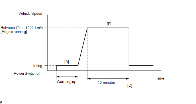
- Start the engine and warm it up (until the engine coolant temperature is 75°C (167°F) or higher) [A].
-
Drive the vehicle at a constant speed between 75 and 100 km/h (47 and 62 mph) for 10 minutes [B].
CAUTION:
When performing the confirmation driving pattern, obey all speed limits and traffic laws.
HINT:
If the engine stops, further depress the accelerator pedal to restart the engine.
-
Check Complete is displayed for O2 Sensor / Current.
HINT:
Check the test values on the Techstream by entering the following menus: Powertrain / Engine / Monitor / Current Monitor / O2 Sensor / Details / RL RESPONSE RATE B1S1, LR RESPONSE RATE B1S1, RL DELAY B1S1 and LR DELAY B1S1.
-
If Complete is not displayed for monitor item O2 Sensor / Current (if the test values indicated on the Techstream do not change), perform Readiness Monitor Drive Pattern for the air fuel ratio sensor (sensor 1) and air fuel ratio sensor (sensor 2).
Click here
- Enter the following menus: Powertrain / Engine / Trouble Codes [C].
-
Read the pending DTCs.
HINT:
- If a pending DTC is output, the system is malfunctioning.
- If a pending DTC is not output, perform the following procedure.
- Enter the following menus: Powertrain / Engine / Utility / All Readiness.
- Input the DTC: P014C00, P014D00, P015A00 or P015B00.
-
Check the DTC judgment result.
Techstream Display
Description
NORMAL
- DTC judgment completed
- System normal
ABNORMAL
- DTC judgment completed
- System abnormal
INCOMPLETE
- DTC judgment not completed
- Perform driving pattern after confirming DTC enabling conditions
HINT:
- If the judgment result is NORMAL, the system is normal.
- If the judgment result is ABNORMAL, the system is malfunctioning.
- If the judgment result is INCOMPLETE, perform steps [B] through [C] again.
-
[A] to [C]: Normal judgment procedure.
The normal judgment procedure is used to complete DTC judgment and also used when clearing permanent DTCs.
- When clearing the permanent DTCs, do not disconnect the cable from the auxiliary battery terminal or attempt to clear the DTCs during this procedure, as doing so will clear the universal trip and normal judgment histories.
WIRING DIAGRAM
Refer to DTC P003012.
Click here
CAUTION / NOTICE / HINT
NOTICE:
- Inspect the fuses for circuits related to this system before performing the following procedure.
-
Vehicle Control History may be stored in the hybrid vehicle control ECU assembly if the engine is malfunctioning. Certain vehicle condition information is recorded when Vehicle Control History is stored. Reading the vehicle conditions recorded in both the Freeze Frame Data and Vehicle Control History can be useful for troubleshooting.
Click here
(Select Powertrain in Health Check and then check the time stamp data.)
Click here
-
If any "Engine Malfunction" Vehicle Control History item has been stored in the hybrid vehicle control ECU assembly, make sure to clear it. However, as all Vehicle Control History items are cleared simultaneously, if any Vehicle Control History items other than "Engine Malfunction" are stored, make sure to perform any troubleshooting for them before clearing Vehicle Control History.
Click here
HINT:
- A low air fuel ratio sensor (sensor 1) current could be caused by a rich air fuel mixture. Check for conditions that would cause the engine to run rich.
- A high air fuel ratio sensor (sensor 1) current could be caused by a lean air fuel mixture. Check for conditions that would cause the engine to run lean.
- Sensor 1 refers to the sensor closest to the engine assembly.
- Sensor 2 refers to the sensor farthest away from the engine assembly.
- Read Freeze Frame Data using the Techstream. The ECM records vehicle and driving condition information as Freeze Frame Data the moment a DTC is stored. When troubleshooting, Freeze Frame Data can be helpful in determining whether the vehicle was moving or stationary, whether the engine was warmed up or not, whether the air fuel ratio was lean or rich, as well as other data recorded at the time of a malfunction.
PROCEDURE
| 1. | CHECK ANY OTHER DTCS OUTPUT (IN ADDITION TO DTC P014C00, P014D00, P015A00 OR P015B00) |
(a) Connect the Techstream to the DLC3.
(b) Turn the power switch on (IG).
(c) Turn the Techstream on.
(d) Enter the following menus: Powertrain / Engine / Trouble Codes.
(e) Read the DTCs.
Powertrain > Engine > Trouble Codes| Result | Proceed to |
|---|---|
| DTC P014C00, P014D00, P015A00 or P015B00 is output | A |
| DTC P014C00, P014D00, P015A00 or P015B00 and other DTCs are output | B |
HINT:
If any DTCs other than P014C00, P014D00, P015A00 or P015B00 are output, troubleshoot those DTCs first.
| B | .gif) | GO TO DTC CHART |
|
.gif)
| 2. | INSPECT AIR FUEL RATIO SENSOR (SENSOR 1) (HEATER RESISTANCE) |
(a) Inspect the air fuel ratio sensor (sensor 1).
Click here
HINT:
Perform "Inspection After Repair" after replacing the air fuel ratio sensor (sensor 1).
Click here
| NG | | REPLACE AIR FUEL RATIO SENSOR (SENSOR 1) |
|
| 3. | CHECK HARNESS AND CONNECTOR (AIR FUEL RATIO SENSOR (SENSOR 1) - ECM) |
(a) Disconnect the air fuel ratio sensor (sensor 1) connector.
(b) Disconnect the ECM connector.
(c) Measure the resistance according to the value(s) in the table below.
Standard Resistance:
| Tester Connection | Condition | Specified Condition |
|---|---|---|
| C72-1 (HA1A) - C88-9 (HA1A) | Always | Below 1 Ω |
| C72-3 (A1A+) - C88-95 (A1A+) | Always | Below 1 Ω |
| C72-4 (A1A-) - C88-94 (A1A-) | Always | Below 1 Ω |
| C72-1 (HA1A) or C88-9 (HA1A) - Body ground and other terminals | Always | 10 kΩ or higher |
| C72-3 (A1A+) or C88-95 (A1A+) - Body ground and other terminals | Always | 10 kΩ or higher |
| C72-4 (A1A-) or C88-94 (A1A-) - Body ground and other terminals | Always | 10 kΩ or higher |
| NG | | REPAIR OR REPLACE HARNESS OR CONNECTOR |
|
| 4. | CLEAR DTC |
(a) Connect the Techstream to the DLC3.
(b) Turn the power switch on (IG).
(c) Turn the Techstream on.
(d) Clear the DTCs.
Powertrain > Engine > Clear DTCs(e) Turn the power switch off and wait for at least 30 seconds.
|
| 5. | CHECK WHETHER DTC OUTPUT RECURS (DTC P014C00, P014D00, P015A00 OR P015B00) |
(a) Drive the vehicle in accordance with the driving pattern described in Confirmation Driving Pattern.
(b) Enter the following menus: Powertrain / Engine / Trouble Codes / Pending.
(c) Read the pending DTCs.
Powertrain > Engine > Trouble Codes| Result | Proceed to |
|---|---|
| DTCs are not output | A |
| DTC P014C00, P014D00, P015A00 or P015B00 is output | B |
| A | | CHECK FOR INTERMITTENT PROBLEMS |
|
| 6. | REPLACE AIR FUEL RATIO SENSOR (SENSOR 1) |
(a) Replace the air fuel ratio sensor (sensor 1).
Click here
HINT:
Perform "Inspection After Repair" after replacing the air fuel ratio sensor (sensor 1).
Click here
|
| 7. | CLEAR DTC |
(a) Connect the Techstream to the DLC3.
(b) Turn the power switch on (IG).
(c) Turn the Techstream on.
(d) Clear the DTCs.
Powertrain > Engine > Clear DTCs(e) Turn the power switch off and wait for at least 30 seconds.
|
| 8. | CHECK WHETHER DTC OUTPUT RECURS (DTC P014C00, P014D00, P015A00 OR P015B00) |
(a) Drive the vehicle in accordance with the driving pattern described in Confirmation Driving Pattern.
(b) Enter the following menus: Powertrain / Engine / Trouble Codes / Pending.
(c) Read the pending DTCs.
Powertrain > Engine > Trouble Codes| Result | Proceed to |
|---|---|
| DTCs are not output | A |
| DTC P014C00, P014D00, P015A00 or P015B00 is output | B |
| A | | END |
| B | | CHECK ENGINE TO DETERMINE CAUSE OF EXTREMELY RICH OR LEAN ACTUAL AIR FUEL RATIO |
READ NEXT:
 System Too Lean Bank 1 (P017100,P017200,P117000,P117B00)
DESCRIPTION The fuel trim is related to the feedback compensation value, not to the basic injection duration. The fuel trim consists of both the short-term and long-term fuel trims. The short-term fue
Fuel Rail Pressure Sensor "A" Circuit Short to Ground (P019011)
DESCRIPTION The fuel pressure sensor (for high pressure side) is installed on the fuel delivery pipe (for high pressure side). The fuel pressure sensor (for high pressure side) changes the fuel press
Fuel Rail Pressure Sensor "A" Circuit Short to Battery or Open (P019015)
DESCRIPTION Refer to DTC P019011. Click here DTC No. Detection Item DTC Detection Condition Trouble Area MIL Memory Note P019015 Fuel Rail Pressure Sensor "A" Circuit Short to B
SEE MORE:
Sensor (Motor) Failure (B2341,B2344)
DESCRIPTION When the sliding roof ECU (sliding roof drive gear assembly) detects a motor malfunction and the sliding roof operation is stopped, DTC B2341 is stored. When the sliding roof ECU (sliding roof drive gear assembly) detects a gear position malfunction and the sliding roof operation is stop
Terminals Of Ecu
TERMINALS OF ECU NOTICE:
DTCs may be output when connectors are disconnected during inspection. Therefore, be sure to clear the DTCs using the Techstream once the inspection has been completed.
Do not apply excessive force to the forward recognition camera connector.
CHECK FORWARD RECOGNITI
