Lexus ES: Removal
REMOVAL
CAUTION / NOTICE / HINT
The necessary procedures (adjustment, calibration, initialization, or registration) that must be performed after parts are removed and installed, or replaced during engine coolant temperature sensor removal/installation are shown below.
Necessary Procedures After Parts Removed/Installed/Replaced| Replaced Part or Performed Procedure | Necessary Procedure | Effect/Inoperative Function when Necessary Procedure not Performed | Link |
|---|---|---|---|
|
*: When performing learning using the Techstream.
Click here | |||
| Auxiliary battery terminal is disconnected/reconnected | Perform steering sensor zero point calibration | Lane Control System (for HV Model) | |
| Pre-collision System (for HV Model) | |||
| Parking Support Brake System (for HV Model)* | |||
| Lighting System (for HV Model) | |||
| Memorize steering angle neutral point | Parking Assist Monitor System (for HV Model) | | |
| Panoramic View Monitor System (for HV Model) | | ||
| Initialize power trunk lid system | Power Trunk Lid System (for HV Model) | | |
| Replacement of inverter with converter assembly | Resolver learning |
| |
| Replacement of ECM | Perform Vehicle Identification Number (VIN) registration | MIL illuminates | |
| Replacement of engine coolant temperature sensor | Inspection after repair |
| |
NOTICE:
- After the power switch is turned off, the radio receiver assembly records various types of memory and settings. As a result, after turning the power switch off, make sure to wait at least 85 seconds before disconnecting the cable from the negative (-) auxiliary battery terminal. (for Audio and Visual System)
- After the power switch is turned off, the radio receiver assembly records various types of memory and settings. As a result, after turning the power switch off, make sure to wait at least 85 seconds before disconnecting the cable from the negative (-) auxiliary battery terminal. (for Navigation System)
PROCEDURE
1. DRAIN ENGINE COOLANT (for Engine)
Click here .gif)
2. REMOVE COOL AIR INTAKE DUCT SEAL
Click here
3. REMOVE INLET AIR CLEANER ASSEMBLY
Click here
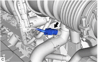
4. REMOVE NO. 2 ENGINE COOLANT TEMPERATURE SENSOR
| (a) Disconnect the No. 2 engine coolant temperature sensor connector. |
|
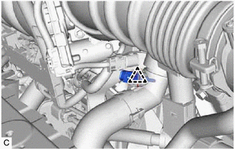
| (b) Remove the clip and No. 2 engine coolant temperature sensor from the radiator pipe. NOTICE: If the No. 2 engine coolant temperature sensor has been struck or dropped, replace it. |
|
5. REMOVE INVERTER WITH CONVERTER ASSEMBLY
Click here
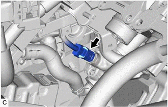
6. REMOVE ENGINE COOLANT TEMPERATURE SENSOR
| (a) Disconnect the engine coolant temperature sensor connector. |
|
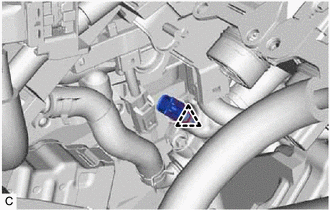
| (b) Remove the clip and engine coolant temperature sensor from the water outlet. NOTICE: If the engine coolant temperature sensor has been struck or dropped, replace it. |
|
READ NEXT:
 Inspection
INSPECTION CAUTION / NOTICE / HINT CAUTION:
Do not put your hands into the water that has been heated for the inspection.
Touching the heated water could result in burns.
PROCEDURE 1. INSPECT
Installation
INSTALLATION PROCEDURE 1. INSTALL ENGINE COOLANT TEMPERATURE SENSOR HINT: Perform "Inspection After Repair" after replacing the engine coolant temperature sensor. Click here (a) Apply a light coa
SEE MORE:
PBD/PTL Closer Switch (B2251)
DESCRIPTION DTC B2251 is output if there is a malfunction in the half latch switch circuit of the luggage door closer assembly. DTC No. Detection Item DTC Detection Condition Trouble Area B2251 PBD/PTL Closer Switch When luggage door is opening or closing, malfunction occurs in half
Installation
INSTALLATION PROCEDURE 1. INSTALL WINDSHIELD WIPER SWITCH ASSEMBLY (a) Engage the claw to install the windshield wiper switch assembly as shown in the illustration. Install in this Direction 2. INSTALL UPPER STEERING COLUMN COVER (a) Engage the claw to install the upper steering column cov
