Lexus ES: Removal
REMOVAL
CAUTION / NOTICE / HINT
The necessary procedures (adjustment, calibration, initialization or registration) that must be performed after parts are removed and installed, or replaced during fuel tank pressure sensor (vapor pressure sensor assembly) removal/installation are shown below.
Necessary Procedures After Parts Removed/Installed/Replaced| Replaced Part or Performed Procedure | Necessary Procedure | Effect/Inoperative Function when Necessary Procedure not Performed | Link |
|---|---|---|---|
|
*: When performing learning using the Techstream.
Click here | |||
| Auxiliary battery terminal is disconnected/reconnected | Perform steering sensor zero point calibration | Lane Control System (for HV Model) | |
| Pre-collision System (for HV Model) | |||
| Parking Support Brake System (for HV Model)* | |||
| Lighting System (for HV Model) | |||
| Memorize steering angle neutral point | Parking Assist Monitor System (for HV Model) | | |
| Panoramic View Monitor System (for HV Model) | | ||
| Initialize power trunk lid system | Power Trunk Lid System (for HV Model) | | |
NOTICE:
- After the power switch is turned off, the radio receiver assembly records various types of memory and settings. As a result, after turning the power switch off, make sure to wait at least 85 seconds before disconnecting the cable from the negative (-) auxiliary battery terminal. (for Audio and Visual System)
- After the power switch is turned off, the radio receiver assembly records various types of memory and settings. As a result, after turning the power switch off, make sure to wait at least 85 seconds before disconnecting the cable from the negative (-) auxiliary battery terminal. (for Navigation System)
PROCEDURE
1. REMOVE REAR SEAT ASSEMBLY
Click here .gif)
2. REMOVE REAR FLOOR SERVICE HOLE COVER
Click here
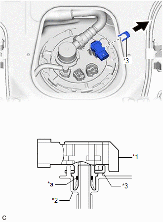
3. REMOVE FUEL TANK PRESSURE SENSOR (VAPOR PRESSURE SENSOR)
| (a) Remove the tube joint clip and pull off the fuel tank pressure sensor (vapor pressure sensor) from the fuel tank assembly. NOTICE:
|
|
READ NEXT:
 Installation
INSTALLATION PROCEDURE 1. INSTALL FUEL TANK PRESSURE SENSOR (VAPOR PRESSURE SENSOR) (a) Push the fuel tank pressure sensor (vapor pressure sensor) onto the fuel tank assembly, then install the tube
Components
COMPONENTS ILLUSTRATION *1 FUEL VAPOR CONTAINMENT VALVE (FUEL TANK SOLENOID MAIN VALVE ASSEMBLY) *2 FUEL TANK VENT HOSE SUB-ASSEMBLY *3 FUEL TANK VENT HOSE - - N*m (kgf*cm,
SEE MORE:
Diagnostic Trouble Code Chart
DIAGNOSTIC TROUBLE CODE CHART Telematics System DTC No. Detection Item Link U014087 Lost Communication with Body Control Module Missing Message U015587 Lost Communication with Instrument Panel Cluster (IPC) Control Module Missing Message U016387 Lost Communication
Reassembly
REASSEMBLY CAUTION / NOTICE / HINT HINT:
Use the same procedure for the RH side and LH side.
The following procedure is for the LH side.
PROCEDURE 1. INSTALL VISOR COVER ASSEMBLY Click here 2. INSTALL OUTER MIRROR UPPER COVER Click here 3. INSTALL OUTER MIRROR LOWER COVER Click here 4.
