Lexus ES: Installation
INSTALLATION
PROCEDURE
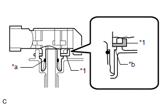
1. INSTALL FUEL TANK PRESSURE SENSOR (VAPOR PRESSURE SENSOR)
| (a) Push the fuel tank pressure sensor (vapor pressure sensor) onto the fuel tank assembly, then install the tube joint clip. NOTICE:
|
|
2. INSTALL REAR FLOOR SERVICE HOLE COVER
Click here .gif)
3. INSTALL REAR SEAT ASSEMBLY
Click here
READ NEXT:
 Components
COMPONENTS ILLUSTRATION *1 FUEL VAPOR CONTAINMENT VALVE (FUEL TANK SOLENOID MAIN VALVE ASSEMBLY) *2 FUEL TANK VENT HOSE SUB-ASSEMBLY *3 FUEL TANK VENT HOSE - - N*m (kgf*cm,
Removal
REMOVAL PROCEDURE 1. REMOVE FUEL VAPOR CONTAINMENT VALVE (FUEL TANK SOLENOID MAIN VALVE ASSEMBLY) (a) Disconnect the fuel vapor containment valve (fuel tank solenoid main valve assembly) connector.
SEE MORE:
Parts Location
PARTS LOCATION ILLUSTRATION *1 MILLIMETER WAVE RADAR SENSOR ASSEMBLY *2 FORWARD RECOGNITION CAMERA *3 BRAKE ACTUATOR ASSEMBLY - SKID CONTROL ECU *4 ECM ILLUSTRATION *1 STOP LIGHT SWITCH ASSEMBLY *2 SPIRAL CABLE WITH SENSOR SUB-ASSEMBLY - SPIRAL CABLE SUB-ASSEMBLY - S
Hybrid/EV Battery Energy Control Module A/D Processing Internal Electronic Failure (P060B49)
DESCRIPTION The battery ECU assembly monitors its internal operation and will store these DTCs when it detects an internal malfunction. DTC No. Detection Item DTC Detection Condition Trouble Area MIL Warning Indicate P060B49 Hybrid/EV Battery Energy Control Module A/D Processing I
© 2016-2026 Copyright www.lexguide.net
