Lexus ES: Removal
REMOVAL
PROCEDURE
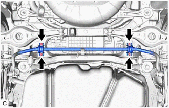
1. REMOVE REAR NO. 1 STABILIZER BAR BRACKET
| (a) Remove the 4 bolts and 2 rear No. 1 stabilizer bar brackets from the vehicle body. |
|
2. REMOVE CANISTER (CHARCOAL CANISTER ASSEMBLY)
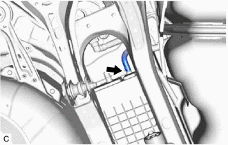
(a) Disconnect the fuel tank vent hose sub-assembly from the leak detection pump sub-assembly.
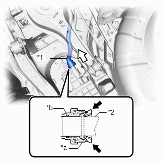
| *1 | Fuel Tank Vent Hose Sub-assembly |
| *2 | Pipe (Leak Detection Pump Sub-assembly) |
| *a | Tube Connector |
| *b | O-ring |
.png) | Pinch |
.png) | Pull off |
NOTICE:
- Remove any dirt or foreign matter on the tube connector before performing this work.
- Perform this work by hand. Do not use any tools.
- Do not forcibly bend, twist or turn the fuel tank vent hose sub-assembly.
- Protect the disconnected parts by covering them with plastic bags after disconnecting the fuel tank vent hose sub-assembly.
- If the tube connector and pipe (leak detection pump sub-assembly) are stuck, push and pull to release them.
(1) Push the fuel tank vent hose sub-assembly firmly toward the leak detection pump sub-assembly.
(2) Pinch the tube connector as shown in the illustration.
(3) Pull off the fuel tank vent hose sub-assembly from the pipe (leak detection pump sub-assembly).
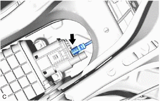
| (b) Disconnect the leak detection pump sub-assembly connector. |
|
(c) Disconnect the fuel tank vent hose from the canister (charcoal canister assembly).
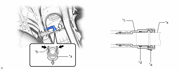
| *a | Retainer | *b | Tab |
| *c | Tube Connector | *d | O-ring |
| *e | Pipe (Canister (Charcoal Canister Assembly)) | - | - |
| | Pinch | | Pull |
NOTICE:
- Remove any dirt or foreign matter on the tube connector before performing this work.
- Do not allow any scratches or foreign matter to get on the parts when disconnecting them as the tube connector has an O-ring that seals the pipe (canister (charcoal canister assembly)).
- Perform this work by hand. Do not use any tools.
- Do not forcibly bend, twist or turn the fuel tank vent hose.
- Protect the disconnected parts by covering them with plastic bags after disconnecting the fuel tank vent hose.
- If the tube connector and pipe (canister (charcoal canister assembly)) are stuck, push and pull to release them.
HINT:
Do not remove the retainer.
(1) Pinch the tabs of the retainer to disengage the lock claws and pull it down.
(2) Pull off the fuel tank vent hose.
| (d) Slide the clip and disconnect the purge line hose from the canister (charcoal canister assembly). |
|
(e) Remove the 2 bolts.
| | Bolt |
| | Clip |
(f) Disengage the clip and disconnect the canister (charcoal canister assembly).
| (g) Disengage the claw and remove the canister (charcoal canister assembly) from vehicle body as shown in the illustration. |
|
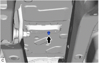
| (h) Remove the clip from the vehicle body. |
|
3. REMOVE LEAK DETECTION PUMP SUB-ASSEMBLY
HINT:
Only perform this procedure when replacement of the leak detection pump sub-assembly is necessary.
(a) Before removing the leak detection pump sub-assembly, clean the charcoal canister sub-assembly by blowing air into it to ensure that the charcoal canister sub-assembly is free of foreign matter.
NOTICE:
- Make sure to clean the charcoal canister sub-assembly using air only.
- Do not use gasoline, thinners or solvents.
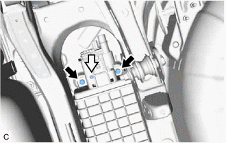
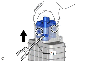
| (b) While disengaging the 2 claws as shown in the illustration, push the leak detection pump sub-assembly upwards using a screwdriver with its tip wrapped with protective tape to remove it. |
|
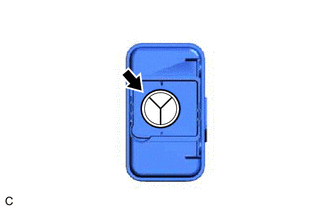
(c) Check if the charcoal canister sub-assembly contains foreign matter such as mud or water.
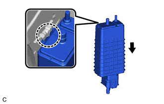
| (1) Visually check that the inside of the charcoal canister sub-assembly is free of foreign matter. |
|
(2) Hold the charcoal canister sub-assembly upside down to make sure that it is free of foreign matter.
If the charcoal canister sub-assembly contains foreign matter, replace the canister (charcoal canister assembly).
READ NEXT:
 Inspection
INSPECTION PROCEDURE 1. INSPECT CANISTER (CHARCOAL CANISTER ASSEMBLY) (a) Visually check the canister (charcoal canister assembly). (1) Visually check the canister (charcoal canister assembly) for
Installation
INSTALLATION PROCEDURE 1. INSTALL LEAK DETECTION PUMP SUB-ASSEMBLY HINT: Only perform this procedure when replacement of the leak detection pump sub-assembly is necessary. (a) Engage the 2 claws to
SEE MORE:
How To Proceed With Troubleshooting
CAUTION / NOTICE / HINT HINT:
Before performing troubleshooting for the dynamic radar cruise control system, perform troubleshooting for the pre-collision system.
Click here
*: Use the Techstream.
PROCEDURE 1. VEHICLE BROUGHT TO WORKSHOP
NEXT 2. PRE-CHECK
GNSS Antenna Circuit Short to Ground (B15C111,B15C113)
DESCRIPTION These DTCs are stored when a malfunction occurs in the telephone and GPS antenna assembly (for Roof Side) circuit. DTC No. Detection Item DTC Detection Condition Trouble Area B15C111 GNSS Antenna Circuit Short to Ground Current to the GNSS antenna is lower than the malfu
