Lexus ES: Inspection
INSPECTION
PROCEDURE
1. INSPECT CANISTER (CHARCOAL CANISTER ASSEMBLY)
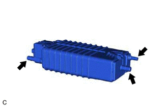
| (a) Visually check the canister (charcoal canister assembly). (1) Visually check the canister (charcoal canister assembly) for cracks or damage. If cracks or damage are found, replace the canister (charcoal canister assembly). |
|
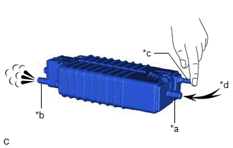
(b) Check the canister (charcoal canister assembly) operation.
| (1) With the purge line port closed, blow 0.5 kPa (0.005 kgf/cm2, 0.1 psi) of air into the vent line port, and check that air flows from the air line port. If the result is not as specified, replace the canister (charcoal canister assembly). |
|
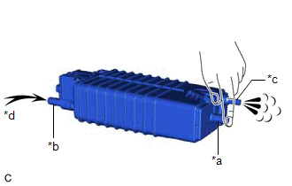
| (2) With the vent line port closed, blow 0.5 kPa (0.005 kgf/cm2, 0.1 psi) of air into the air line port, and check that air flows from the purge line port. If the result is not as specified, replace the canister (charcoal canister assembly). |
|
(c) Check for air leaks.
| (1) Connect a pressure gauge to the vent line port. |
|
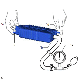
(2) With the purge line port, air line port and leak detection pump sub-assembly connector closed, apply 20 kPa (150 mmHg, 5.91 in. Hg) of pressurized air into the vent line port, then confirm that pressure is maintained for 1 minute.
If the result is not as specified, replace the canister (charcoal canister assembly).
(d) Check the leak detection pump sub-assembly.
| (1) Connect a positive (+) auxiliary battery lead to terminal 5 and a negative (-) auxiliary battery lead to terminal 1. |
|
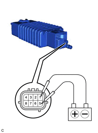
(2) Check that a clicking sound is heard from the leak detection pump sub-assembly.
If the result is not as specified, replace the leak detection pump sub-assembly.
READ NEXT:
 Installation
INSTALLATION PROCEDURE 1. INSTALL LEAK DETECTION PUMP SUB-ASSEMBLY HINT: Only perform this procedure when replacement of the leak detection pump sub-assembly is necessary. (a) Engage the 2 claws to
Components
COMPONENTS ILLUSTRATION *1 EGR COOLER ASSEMBLY *2 EGR VALVE GASKET *3 EGR COOLER GASKET *4 NO. 4 WATER BY-PASS HOSE *5 NO. 3 WATER BY-PASS HOSE - - N*m (kgf*cm, ft
SEE MORE:
Switch Failure (B2342)
DESCRIPTION This DTC is stored when the sliding roof ECU (sliding roof drive gear assembly) detects that the panoramic moon roof switch (map light sub-assembly) is stuck for 30 seconds or more. DTC No. Detection Item DTC Detection Condition Trouble Area B2342 Switch Failure Sliding
Reassembly
REASSEMBLY PROCEDURE 1. INSTALL STEERING LOCK ACTUATOR ASSEMBLY NOTICE: After replacing the steering lock actuator assembly, perform registration. (a) Secure the steering column assembly in a vise between aluminum plates. NOTICE: Do not overtighten the vise. (b) Temporarily install the steering lock
