Lexus ES: Installation
INSTALLATION
PROCEDURE
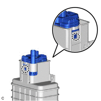
1. INSTALL LEAK DETECTION PUMP SUB-ASSEMBLY
HINT:
Only perform this procedure when replacement of the leak detection pump sub-assembly is necessary.
| (a) Engage the 2 claws to install a new leak detection pump sub-assembly to the charcoal canister sub-assembly. NOTICE:
|
|
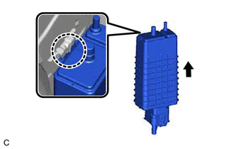
2. INSTALL CANISTER (CHARCOAL CANISTER ASSEMBLY)
(a) Install the clip to the vehicle body.
| (b) Engage the claw to install the canister (charcoal canister assembly) to the vehicle body as shown in the illustration. |
|
(c) Engage the clip to connect the canister (charcoal canister assembly).
(d) Install the 2 bolts.
Torque:
8.0 N·m {82 kgf·cm, 71 in·lbf}
(e) Connect the purge line hose to the canister (charcoal canister assembly) and slide the clip to secure it.
(f) Push the fuel tank vent hose onto the canister (charcoal canister assembly) and push in the retainer to engage the lock claws.
NOTICE:
- Check that there are no scratches or foreign matter around the connecting parts of the tube connector and pipe (canister (charcoal canister assembly)) before performing this work.
- After connecting the fuel tank vent hose, check that the fuel tank vent hose is securely connected by pulling on the tube connector.
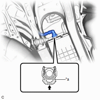
| *a | Retainer |
.png) | Push in |
(g) Connect the leak detection pump sub-assembly connector.
(h) Push in the fuel tank vent hose sub-assembly to the pipe (leak detection pump sub-assembly) until the fuel tank vent hose sub-assembly makes a "click" sound.
NOTICE:
- Check that there are no scratches or foreign matter around the connecting parts of the tube connector and pipe (leak detection pump sub-assembly) before performing this work.
- After connecting the fuel tank vent hose sub-assembly, check that the fuel tank vent hose sub-assembly is securely connected by pulling on the tube connector.
3. INSTALL REAR NO. 1 STABILIZER BAR BRACKET
(a) Install the 2 rear No. 1 stabilizer bar brackets to the vehicle body with the 4 bolts.
Torque:
78 N·m {795 kgf·cm, 58 ft·lbf}
READ NEXT:
 Components
COMPONENTS ILLUSTRATION *1 EGR COOLER ASSEMBLY *2 EGR VALVE GASKET *3 EGR COOLER GASKET *4 NO. 4 WATER BY-PASS HOSE *5 NO. 3 WATER BY-PASS HOSE - - N*m (kgf*cm, ft
Removal
REMOVAL CAUTION / NOTICE / HINT The necessary procedures (adjustment, calibration, initialization or registration) that must be performed after parts are removed and installed, or replaced during EGR
SEE MORE:
Removal
REMOVAL CAUTION / NOTICE / HINT The necessary procedures (adjustment, calibration, initialization, or registration) that must be performed after parts are removed, installed, or replaced during brake pedal stroke sensor assembly removal/installation are shown below. Necessary Procedures After Parts
Power Window Motor Malfunction (B2311)
DESCRIPTION The power window regulator motor assemblies are operated by the multiplex network master switch assembly, power window regulator switch assembly or rear power window regulator switch assemblies. The power window regulator motor assemblies have motor, regulator and ECU functions. This DTC
