Lexus ES: Removal
REMOVAL
CAUTION / NOTICE / HINT
The necessary procedures (adjustment, calibration, initialization or registration) that must be performed after parts are removed and installed, or replaced during radiator assembly removal/installation are shown below.
Necessary Procedure After Parts Removed/Installed/Replaced| Replaced Part or Performed Procedure | Necessary Procedure | Effect/Inoperative Function when Necessary Procedure not Performed | Link |
|---|---|---|---|
| Front bumper assembly |
|
| |
| Front television camera view adjustment | Panoramic View Monitor System | for Initialization for Calibration | |
| Headlight ECU sub-assembly LH |
| Lighting system | |
| Change grille shutter control mode and/or perform initialization | Grille Shutter system | |
PROCEDURE
1. REMOVE FRONT WHEEL OPENING EXTENSION PAD LH
Click here .gif)
2. REMOVE FRONT WHEEL OPENING EXTENSION PAD RH
Click here
3. REMOVE NO. 1 ENGINE UNDER COVER
Click here
4. REMOVE NO. 2 ENGINE UNDER COVER ASSEMBLY
Click here
5. DRAIN ENGINE COOLANT (for Engine)
Click here
6. REMOVE INVERTER WATER PUMP ASSEMBLY
Click here
7. REMOVE HEADLIGHT ASSEMBLY
for LED Type Turn Signal Light: Click here
for Bulb Type Turn Signal Light: Click here
8. REMOVE FRONT BUMPER ENERGY ABSORBER
Click here
9. REMOVE NO. 2 FRONT BUMPER MOUNTING BRACKET
Click here
10. REMOVE FRONT BUMPER REINFORCEMENT SUB-ASSEMBLY
Click here
11. REMOVE RADIATOR SHUTTER SUB-ASSEMBLY
Click here
12. REMOVE VEHICLE APPROACHING SPEAKER ASSEMBLY
Click here
13. REMOVE HOOD LOCK ASSEMBLY
Click here
14. REMOVE INLET AIR CLEANER ASSEMBLY
Click here
15. REMOVE UPPER RADIATOR MOUNTING BRACKET
| (a) Disconnect the 2 horn connectors. |
|
.png)
| (b) Remove the 2 bolts, 2 nuts and 2 upper radiator mounting brackets. |
|
.png)
16. REMOVE NO. 1 RADIATOR AIR GUIDE LH
| (a) Remove the clip and disengage the claw. |
|
(b) Disengage the guide to remove the No. 1 radiator air guide LH.
17. REMOVE NO. 1 RADIATOR AIR GUIDE RH
| (a) Remove the clip and disengage the claw. |
|
(b) Disengage the guide to remove the No. 1 radiator air guide RH.
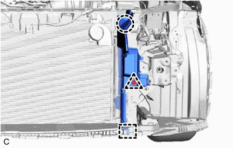
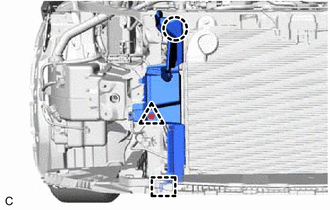
18. REMOVE UPPER RADIATOR SUPPORT SUB-ASSEMBLY
| (a) Disengage the clamp to disconnect the hood lock control cable assembly from the upper radiator support sub-assembly. |
|
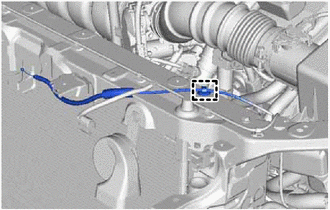
| (b) Disengage the 4 clamps to disconnect the wire harness from the upper radiator support sub-assembly. |
|
.png)
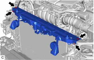
| (c) Remove the 4 bolts and upper radiator support sub-assembly. |
|
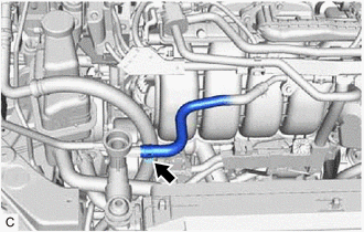
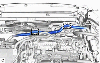
19. DISCONNECT NO. 5 WATER BY-PASS HOSE
| (a) Slide the clip and disconnect the No. 5 water by-pass hose from the radiator assembly. |
|
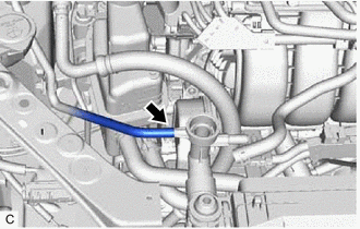
20. DISCONNECT NO. 6 WATER BY-PASS HOSE
| (a) Disconnect the No. 6 water by-pass hose from the radiator assembly. |
|
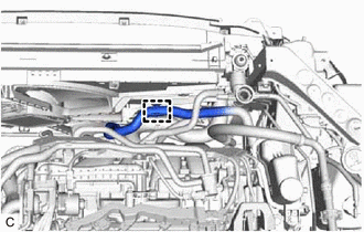
21. DISCONNECT NO. 1 RADIATOR HOSE
| (a) Disengage the clamp and disconnect the No. 1 radiator hose from the fan with motor assembly. |
|
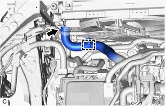
(b) Slide the clip and disconnect the No. 1 radiator hose from the radiator assembly.
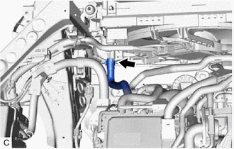
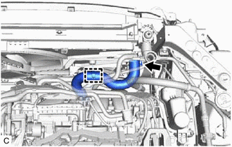
22. DISCONNECT NO. 4 INVERTER COOLING HOSE
| (a) Slide the clip and disconnect the No. 4 inverter cooling hose from the radiator assembly. |
|
23. DISCONNECT NO. 5 INVERTER COOLING HOSE
| (a) Disengage the 2 clamps and disconnect the No. 5 inverter cooling hose from the fan with motor assembly. |
|
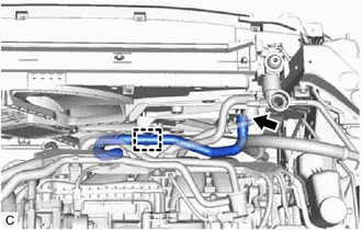
24. DISCONNECT NO. 2 INVERTER COOLING HOSE
| (a) Disengage the clamp and disconnect the No. 2 inverter cooling hose from the fan with motor assembly. |
|
25. DISCONNECT NO. 2 RADIATOR HOSE
| (a) Disengage the clamp and disconnect the No. 2 radiator hose from the fan with motor assembly. |
|
(b) Slide the clip and disconnect the No. 2 radiator hose from the radiator assembly.
26. REMOVE NO. 3 INVERTER COOLING HOSE
| (a) Disengage the clamp and disconnect the No. 3 inverter cooling hose from the fan fan with motor assembly. |
|
(b) Slide the clip and remove the No. 3 inverter cooling hose from the radiator assembly.
27. REMOVE RADIATOR ASSEMBLY
| (a) Disengage the 4 clamps to disconnect the wire harness from the fan with motor assembly. |
|
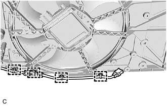
| (b) Disconnect the cooling fan motor connector. |
|
.png)
(c) Disengage the wire harness clamp.
| (d) Rotate the lever while pushing the lock, and disconnect the cooling fan motor connector. NOTICE: After disconnecting the cooling fan motor connector, make sure that dirt, water or other foreign matter does not contact the connecting parts of the cooling fan motor connector. |
|
.png)
(e) Disengage the wire harness clamp.
| (f) Disengage the 2 claws. |
|
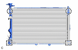
(g) Disengage the 2 guides to separate the cooler condenser assembly from the radiator assembly.
NOTICE:
Make sure not to damage the cooler condenser assembly when separating the cooler condenser assembly.
(h) Remove the radiator assembly with the fan with motor assembly from the vehicle body.
NOTICE:
Do not apply excessive force to the cooler condenser assembly or pipe when removing the radiator assembly with the fan with motor assembly.
| (i) Disengage the 2 claws. |
|
.png)
(j) Disengage the 2 guides to remove the fan with motor assembly from the radiator assembly.
NOTICE:
Do not damage the radiator assembly when removing the fan with motor assembly.
28. REMOVE RADIATOR SUPPORT CUSHION
(a) Remove the 2 radiator support cushions from the radiator assembly.
29. REMOVE LOWER RADIATOR SUPPORT
(a) Remove the 2 lower radiator supports from the radiator assembly.
READ NEXT:
 Installation
INSTALLATION PROCEDURE 1. INSTALL LOWER RADIATOR SUPPORT (a) Install the 2 lower radiator supports to the radiator assembly. 2. INSTALL RADIATOR SUPPORT CUSHION (a) Install the 2 radiator support cush
Components
COMPONENTS ILLUSTRATION *1 NO. 2 RADIATOR HOSE *2 WATER INLET WITH THERMOSTAT SUB-ASSEMBLY *3 GASKET *4 NO. 7 WATER BY-PASS HOSE N*m (kgf*cm, ft.*lbf): Specified torque â—
SEE MORE:
Removal
REMOVAL CAUTION / NOTICE / HINT The necessary procedures (adjustment, calibration, initialization, or registration) that must be performed after parts are removed and installed, or replaced during rack and pinion power steering gear assembly removal/installation are shown below. Necessary Procedure
Components
COMPONENTS ILLUSTRATION *A w/o Manual (SOS) Switch *B w/ Manual (SOS) Switch *1 ANTENNA CORD SUB-ASSEMBLY *2 NO. 2 SIDE DEFROSTER NOZZLE DUCT *3 NO. 3 HEATER TO REGISTER DUCT - - ILLUSTRATION *A for Moon Roof - - *1 NO. 2 ANTENNA CORD SUB-ASSEMBLY -
