Lexus ES: Components
Lexus ES (XZ10) Service Manual / Audio & Visual & Telematics / Audio / Video / Radio Antenna Cord / Components
COMPONENTS
ILLUSTRATION
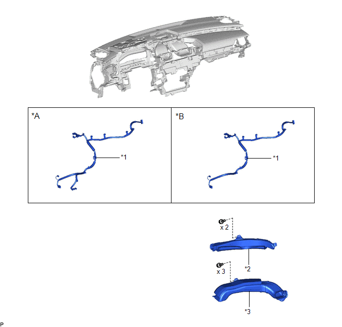
| *A | w/o Manual (SOS) Switch | *B | w/ Manual (SOS) Switch |
| *1 | ANTENNA CORD SUB-ASSEMBLY | *2 | NO. 2 SIDE DEFROSTER NOZZLE DUCT |
| *3 | NO. 3 HEATER TO REGISTER DUCT | - | - |
ILLUSTRATION
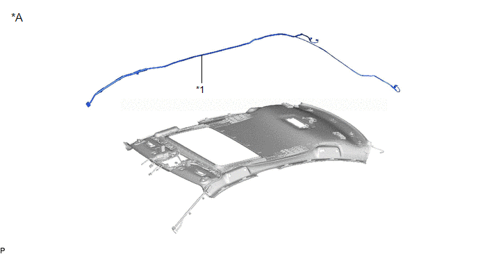
| *A | for Moon Roof | - | - |
| *1 | NO. 2 ANTENNA CORD SUB-ASSEMBLY | - | - |
ILLUSTRATION
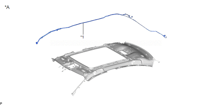
| *A | for Panoramic Moon Roof | - | - |
| *1 | NO. 2 ANTENNA CORD SUB-ASSEMBLY | - | - |
ILLUSTRATION
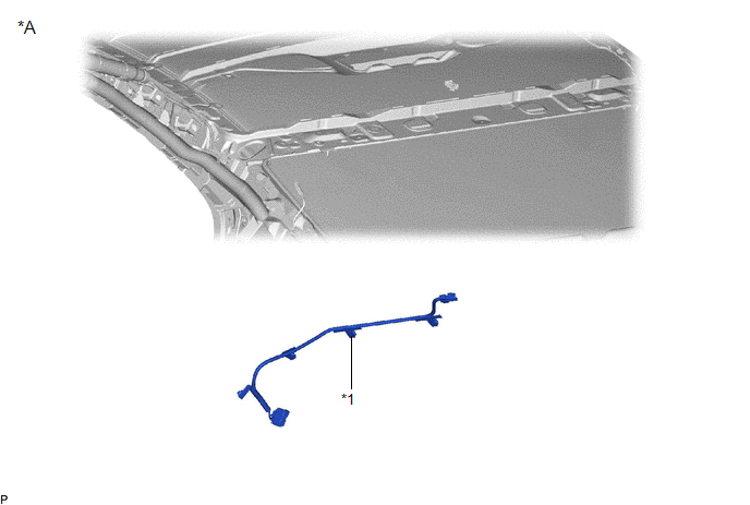
| *A | w/ Manual (SOS) Switch | - | - |
| *1 | NO. 3 ANTENNA CORD SUB-ASSEMBLY | - | - |
READ NEXT:
 Installation
INSTALLATION PROCEDURE 1. INSTALL NO. 3 ANTENNA CORD SUB-ASSEMBLY (w/ Manual (SOS) Switch) (a) Engage the 5 clamps to install the No. 3 antenna cord sub-assembly. (b) Connect the connector. 2. INSTALL
Removal
REMOVAL CAUTION / NOTICE / HINT The necessary procedures (adjustment, calibration, initialization, or registration) that must be performed after parts are removed and installed, or replaced during ant
SEE MORE:
Installation
INSTALLATION PROCEDURE 1. INSTALL REAR NO. 1 DIFFERENTIAL MOUNT CUSHION (a) Using SST, install a new rear No. 1 differential mount cushion. SST: 09316-12010 SST: 09570-24011 *1 Rear Suspension Member Sub-assembly - - *a -3° to 3° *b 9.8 to 10.8 mm (0.3858 to 0.4252 in.) *c
How To Proceed With Troubleshooting
HOW TO PROCEED WITH TROUBLESHOOTING
OPERATION FLOW
HINT:
Perform troubleshooting in accordance with the procedure below. The following
is an outline of basic troubleshooting procedure. Confirm the troubleshooting procedure
for the circuit you are working on before beginning troubleshooting.
© 2016-2026 Copyright www.lexguide.net
