Lexus ES: Removal
REMOVAL
CAUTION / NOTICE / HINT
NOTICE:
This procedure includes the removal of small-head bolts. Refer to Small-Head Bolts of Basic Repair Hint to identify the small-head bolts.
Click here .gif)
PROCEDURE
1. REMOVE NO. 1 ENGINE COVER SUB-ASSEMBLY
Click here
2. REMOVE CAMSHAFT POSITION SENSOR (for Intake Side)
| (a) Disconnect the camshaft position sensor connector. |
|
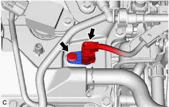
(b) Using an 8 mm socket wrench, remove the bolt and camshaft position sensor from the cylinder head cover sub-assembly.
NOTICE:
If the camshaft position sensor has been struck or dropped, replace it.
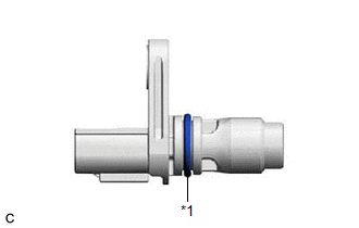
| (c) Perform this procedure only when reusing the camshaft position sensor. (1) Remove the O-ring from the camshaft position sensor. NOTICE:
|
|
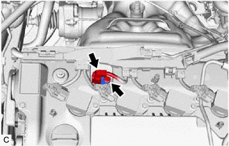
3. REMOVE CAMSHAFT POSITION SENSOR (for Exhaust Side)
(a) Disconnect the camshaft position sensor connector.
| (b) Using an 8 mm socket wrench, remove the bolt and camshaft position sensor from the cylinder head cover sub-assembly. NOTICE: If the camshaft position sensor has been struck or dropped, replace it. |
|
| (c) Perform this procedure only when reusing the camshaft position sensor. (1) Remove the O-ring from the camshaft position sensor. NOTICE:
|
|
READ NEXT:
 Installation
INSTALLATION CAUTION / NOTICE / HINT NOTICE: This procedure includes the installation of small-head bolts. Refer to Small-Head Bolts of Basic Repair Hint to identify the small-head bolts. Click here
On-vehicle Inspection
ON-VEHICLE INSPECTION PROCEDURE 1. INSPECT CAM TIMING CONTROL MOTOR WITH EDU ASSEMBLY (a) Check Rotation Direction Signal: (1) Connect the Techstream to the DLC3. (2) Turn the engine switch on (IG). (
SEE MORE:
Fail-safe Chart
FAIL-SAFE CHART HINT: If the power source voltage to the multiplex tilt and telescopic ECU returns to normal within 10 seconds during tilt or telescopic operation, the operation will be resumed. If it returns to normal after 10 seconds have elapsed, the operation restarts when a tilt or telescopic o
Multiplex Tilt And Telescopic Ecu
ComponentsCOMPONENTS ILLUSTRATION *1 LOWER STEERING COLUMN COVER SUB-ASSEMBLY *2 MULTIPLEX TILT AND TELESCOPIC ECU RemovalREMOVAL PROCEDURE 1. CHANGE POWER TILT AND POWER TELESCOPIC STEERING COLUMN SYSTEM SETTINGS Click here 2. REMOVE LOWER STEERING COLUMN COVER SUB-ASSEMBLY Click
