Lexus ES: Installation
INSTALLATION
CAUTION / NOTICE / HINT
NOTICE:
This procedure includes the installation of small-head bolts. Refer to Small-Head Bolts of Basic Repair Hint to identify the small-head bolts.
Click here .gif)
PROCEDURE
1. INSTALL CAMSHAFT POSITION SENSOR (for Exhaust Side)
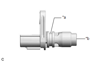
| *a | O-ring Groove |
| *b | Camshaft Position Sensor Tip |
(a) Perform this procedure only when reusing the camshaft position sensor.
(1) Clean the O-ring groove of the camshaft position sensor.
NOTICE:
Make sure the O-ring groove is free of foreign matter.
(2) Install a new O-ring to the camshaft position sensor.
NOTICE:
Set the O-ring on the tip of the camshaft position sensor and roll it into the O-ring groove with bare hands to install it.
| (3) Check if the O-ring is twisted. HINT: Check the entire circumference of the seam of the O-ring for twisting. |
|
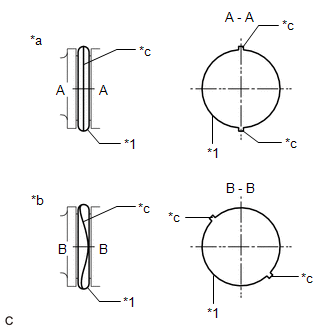
(b) Apply a light coat of engine oil to the O-ring of the camshaft position sensor.
(c) Using an 8 mm socket wrench, install the camshaft position sensor to the cylinder head cover sub-assembly with a new bolt.
Torque:
7.5 N·m {76 kgf·cm, 66 in·lbf}
NOTICE:
- If the camshaft position sensor has been struck or dropped, replace it.
- Make sure that the O-ring is not cracked or moved out of place when installing the camshaft position sensor.
(d) Connect the camshaft position sensor connector.
2. INSTALL CAMSHAFT POSITION SENSOR (for Intake Side)
| *a | O-ring Groove |
| *b | Camshaft Position Sensor Tip |
(a) Perform this procedure only when reusing the camshaft position sensor.
(1) Clean the O-ring groove of the camshaft position sensor.
NOTICE:
Make sure the O-ring groove is free of foreign matter.
(2) Install a new O-ring to the camshaft position sensor.
NOTICE:
Set the O-ring on the tip of the camshaft position sensor and roll it into the O-ring groove with bare hands to install it.
| (3) Check if the O-ring is twisted. HINT: Check the entire circumference of the seam of the O-ring for twisting. |
|
(b) Apply a light coat of engine oil to the O-ring of the camshaft position sensor.
(c) Using an 8 mm socket wrench, install the camshaft position sensor to the cylinder head cover sub-assembly with a new bolt.
Torque:
7.5 N·m {76 kgf·cm, 66 in·lbf}
NOTICE:
- If the camshaft position sensor has been struck or dropped, replace it.
- Make sure that the O-ring is not cracked or moved out of place when installing the camshaft position sensor.
(d) Connect the camshaft position sensor connector.
3. INSPECT FOR ENGINE OIL LEAK
Click here
4. INSTALL NO. 1 ENGINE COVER SUB-ASSEMBLY
Click here
READ NEXT:
 On-vehicle Inspection
ON-VEHICLE INSPECTION PROCEDURE 1. INSPECT CAM TIMING CONTROL MOTOR WITH EDU ASSEMBLY (a) Check Rotation Direction Signal: (1) Connect the Techstream to the DLC3. (2) Turn the engine switch on (IG). (
Inspection
INSPECTION CAUTION / NOTICE / HINT NOTICE:
Make sure the contact surface of the cam timing control motor with EDU assembly (the surface that contacts the No. 2 timing gear cover assembly) is free o
SEE MORE:
How To Proceed With Troubleshooting
CAUTION / NOTICE / HINT HINT:
Use the following procedure to troubleshoot the LEXUS ENFORM system.
*: Use the Techstream.
PROCEDURE 1. VEHICLE BROUGHT TO WORKSHOP
NEXT 2. CHECK THE CUSTOMER'S CONTRACT STATUS (a) Check if the satellite radio and LEXUS ENFORM
System Description
SYSTEM DESCRIPTION ACTIVE NOISE CONTROL SYSTEM (a) The active noise control system is a system that detects muffled engine sounds produced in sync that fluctuates according to the engine speed, by using the active noise control microphone and outputs anti-phase control sound through the audio speake
